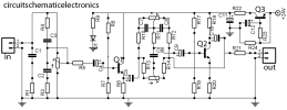
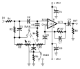
Stereo tone control with loudness and filter circuit diagram

Part list :
R1 = 100K
R2 = 50K trim
R3 = 22K
R4 = 15K
R5 = 1K
R6 = 4K7
R7 = 330K
R8 = 330K
R9 = 3K3
R10= 5K6
R11= 8K2
R12= 5K6
R13= 1K
R14= 1K
R15= 50K TRIM
R16= 50K TRIM
R17= 330K
R18= 4K7
R19= 47K
R20= 1K
R21= 4K7
R22= 2K2
R23= 100R
R24= 22K
C1 = 15n
C2 = 15n
C3 = 560p
C4 = 4u7
C5 = 33u
C6 = 4n7
C7 = 39n
C8 = 39n
C9 = 4u7
C10=4u7
C11=470u
C12=100u
Q1 = C1815
Q2 = C828
D1 = Green Led


