Stereokodér

Dále popsané zařízení je jednoduchý stereokodér pro multiplexní provoz. Dá se spojit se libovolným VKV vysílačem.

Multiplexní kódování
Celý problém spočívá v tom jak, jak spojit dva signály v jeden a na přijímací straně zase oddělit. U komerčních rádií v pásmu VKV se používá tzv. multiplexní kódování. Tento princip spočívá ve střídavém připojování levého a pravého kanálu ke vstupu modulátoru vysílače. Přepínací frekvence je stanovena na 38kHz. Na přijímací straně se multiplexní signál střídavě přepíná do levého a pravého kanálu. Přijímač pochopitelně nemůže přepínat signál na libovolné frekvenci, ale musí být fázově synchronizován s vysílací stranou. K tomuto účelu slouží na přijímací straně fázový zavěs (PLL), který je "zavěšen" na tzv. pilotním signálu 19kHz přidávaným do vysílaného signálu v stereokodéru. Tento signál je přepínací kmitočet 38kHz dělený dvěma a vyfiltrovaný na sinus.
Popis funkce
Jako oscilátor jsem použil obvod 4046. Ladící napětí je stabilizované zenerkou. Oscilátor produkuje kmitočet 76 kHz. Jako dělič frekvence jsem použil obvod D-klopný obvod 4013. Nejprve se kmitočet oscilátoru dělí dvěma na 38 kHz. Tento kmitočet je veden do elektronického přepínače IC3. Signál je veden jednak přímo do IC3c, dále do IC3d který slouží jako invertor a z jeho výstupu na IC3b. Spínače IC3a a IC3c tedy střídavě připojují levý a pravý kanál k bázi oddělovacího tranzistoru. Signál 38 kHz se dále dělí dvěma v dalším KO. V stup KO však musí být připojen přes integrační člen R6, C6, který posouvá fázi signálu. Bez tohoto fázovacího členu by byl stereofonní efekt jen nepatrný. Pilotní kmitočet 19 kHz se odebírá z výstupu druhého KO. Signál je přiveden na trimr P2, kterým se reguluje jeho intenzita. Filtr složený ze součástek C7, C8, C9, R4 a R5 vyfiltruje obdélníkový signál na docela solidní sinus, který je přes C3 veden do emitoru výstupního zesilovače. Přivedení signálu do emitoru je výhodné v tom, že se tolik neovlivňuje s vlastním zvukem vedeným do báze. Součástky kolem T1 nastavují a stabilizují jeho pracovní bod. Mezi vstupy a přepínač jsou zapojeny operáky. Zesílení je regulovatelné od útlumu 50x po zesílení 22x zvlášť pro každý kanál. Odběr je díky CMOS obvodům velmi nízký.

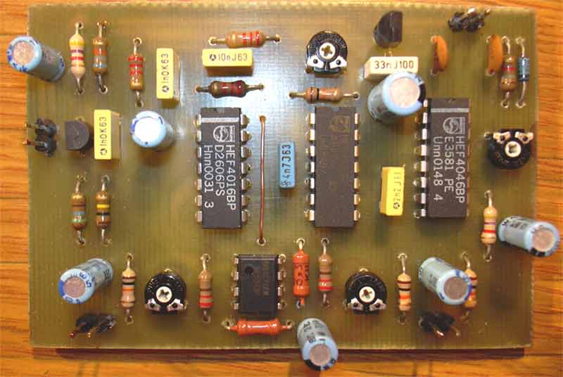
Osazovací plán, DPS v rozlišení 300 dpi
Oživení
Nastavení je velice jednoduché. Výstup OUT připojíme na vstup nějakého vysílače, vstupy prozatím nezapojujeme. Je-li k dispozici čítač, nastavíme pomocí P1 kmitočet IC1 na 76 kHz. Dále připojíme vstupní signály na vstupy L a R. Intenzitu signálu nastavíme těsně pod limitaci (projeví se silným zkreslením). Dále pomocí P2 nastavíme intenzitu pilotního signálu. V mém případě to byla asi polovina odporové dráhy, ale záleží to na citlivosti vysílače. U T1 bude možná nutné upravit nastavení pracovního bodu. Je to dáno rozptylem parametrů tranzistorů. pravu lze provést například změnou hodnoty R17, tak aby na kolektoru byla zhruba polovina napájecího napětí (4.5V). Ve zkušebním vzorku na kontaktním poli vyhověly uvedené hodnoty, ale v dalším vzorku jsem musel odpor snížit asi o třetinu.
V případě, že není k dispozici čítač, nastaví se frekvence oscilátoru zkusmo pomalým otáčením P1, dokud se nerozsvítí indikátor stereofonního vysílání. P2 se musí v tomto případě před laděním nastavit zhruba do poloviny.
Konstrukční řešení
Celé zapojení je dosti citlivé na vf pole vysílače, takže se vyplatí desku stereokodéru stínit třeba tenkým plechem a nejlépe shora zakrytovat.
Seznam součástek
R1 1k
R2, R15 4k7
R3, R6, R10, R12 10k
R4, R5, R7, R8, R9 2k2
R11, R13 220
R14 560
R16, R17 220k*
C1, C2 100nF
C3 47uF
C4 1uF
C5 2n2
C6 4n7
C7 47nF
C8 10nF
C9, C10 1n5
C13 4u7
C11, C12, C14, C15 10uF
IC1 4046
IC2 4013
IC3 4016, 4066
IC4 NE5532N, NE5532AN, TL072, ...
IC5 78L09
Dále popsané zařízení je jednoduchý stereokodér pro multiplexní provoz. Dá se spojit se libovolným VKV vysílačem.
Multiplexní kódování
Celý problém spočívá v tom jak, jak spojit dva signály v jeden a na přijímací straně zase oddělit. U komerčních rádií v pásmu VKV se používá tzv. multiplexní kódování. Tento princip spočívá ve střídavém připojování levého a pravého kanálu ke vstupu modulátoru vysílače. Přepínací frekvence je stanovena na 38kHz. Na přijímací straně se multiplexní signál střídavě přepíná do levého a pravého kanálu. Přijímač pochopitelně nemůže přepínat signál na libovolné frekvenci, ale musí být fázově synchronizován s vysílací stranou. K tomuto účelu slouží na přijímací straně fázový zavěs (PLL), který je "zavěšen" na tzv. pilotním signálu 19kHz přidávaným do vysílaného signálu v stereokodéru. Tento signál je přepínací kmitočet 38kHz dělený dvěma a vyfiltrovaný na sinus.
Popis funkce
Jako oscilátor jsem použil obvod 4046. Ladící napětí je stabilizované zenerkou. Oscilátor produkuje kmitočet 76 kHz. Jako dělič frekvence jsem použil obvod D-klopný obvod 4013. Nejprve se kmitočet oscilátoru dělí dvěma na 38 kHz. Tento kmitočet je veden do elektronického přepínače IC3. Signál je veden jednak přímo do IC3c, dále do IC3d který slouží jako invertor a z jeho výstupu na IC3b. Spínače IC3a a IC3c tedy střídavě připojují levý a pravý kanál k bázi oddělovacího tranzistoru. Signál 38 kHz se dále dělí dvěma v dalším KO. V stup KO však musí být připojen přes integrační člen R6, C6, který posouvá fázi signálu. Bez tohoto fázovacího členu by byl stereofonní efekt jen nepatrný. Pilotní kmitočet 19 kHz se odebírá z výstupu druhého KO. Signál je přiveden na trimr P2, kterým se reguluje jeho intenzita. Filtr složený ze součástek C7, C8, C9, R4 a R5 vyfiltruje obdélníkový signál na docela solidní sinus, který je přes C3 veden do emitoru výstupního zesilovače. Přivedení signálu do emitoru je výhodné v tom, že se tolik neovlivňuje s vlastním zvukem vedeným do báze. Součástky kolem T1 nastavují a stabilizují jeho pracovní bod. Mezi vstupy a přepínač jsou zapojeny operáky. Zesílení je regulovatelné od útlumu 50x po zesílení 22x zvlášť pro každý kanál. Odběr je díky CMOS obvodům velmi nízký.
Osazovací plán, DPS v rozlišení 300 dpi
Oživení
Nastavení je velice jednoduché. Výstup OUT připojíme na vstup nějakého vysílače, vstupy prozatím nezapojujeme. Je-li k dispozici čítač, nastavíme pomocí P1 kmitočet IC1 na 76 kHz. Dále připojíme vstupní signály na vstupy L a R. Intenzitu signálu nastavíme těsně pod limitaci (projeví se silným zkreslením). Dále pomocí P2 nastavíme intenzitu pilotního signálu. V mém případě to byla asi polovina odporové dráhy, ale záleží to na citlivosti vysílače. U T1 bude možná nutné upravit nastavení pracovního bodu. Je to dáno rozptylem parametrů tranzistorů. pravu lze provést například změnou hodnoty R17, tak aby na kolektoru byla zhruba polovina napájecího napětí (4.5V). Ve zkušebním vzorku na kontaktním poli vyhověly uvedené hodnoty, ale v dalším vzorku jsem musel odpor snížit asi o třetinu.
V případě, že není k dispozici čítač, nastaví se frekvence oscilátoru zkusmo pomalým otáčením P1, dokud se nerozsvítí indikátor stereofonního vysílání. P2 se musí v tomto případě před laděním nastavit zhruba do poloviny.
Konstrukční řešení
Celé zapojení je dosti citlivé na vf pole vysílače, takže se vyplatí desku stereokodéru stínit třeba tenkým plechem a nejlépe shora zakrytovat.
Seznam součástek
R1 1k
R2, R15 4k7
R3, R6, R10, R12 10k
R4, R5, R7, R8, R9 2k2
R11, R13 220
R14 560
R16, R17 220k*
C1, C2 100nF
C3 47uF
C4 1uF
C5 2n2
C6 4n7
C7 47nF
C8 10nF
C9, C10 1n5
C13 4u7
C11, C12, C14, C15 10uF
IC1 4046
IC2 4013
IC3 4016, 4066
IC4 NE5532N, NE5532AN, TL072, ...
IC5 78L09
Eklentiler
Son düzenleme:


