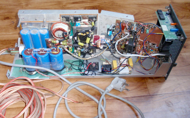
3–60 V / 40 A 2400 W Yüksek Güçlü Ayarlanabilir SMPS
Bu anahtarlamalı güç kaynağı, laboratuvar çalışmaları için yüksek güçlü ve ayarlanabilir bir DC güç kaynağına ihtiyaç duyulduğu için tasarlanmıştır.Bu güç seviyesinde lineer regülatör kullanmak pratik değildir. Çünkü maksimum güç yaklaşık 2400 W (2,4 kW) seviyesindedir. Bu nedenle anahtarlamalı güç kaynağı (SMPS) topolojisi tercih edilmiştir.
Devrede iki anahtarlı ileri dönüştürücü (Two-Switch Forward / Half-Controlled Bridge) topolojisi kullanılmıştır. Anahtarlama elemanları olarak IGBT'ler görev yaparken kontrol işlemi UC3845 PWM kontrol entegresi tarafından gerçekleştirilir.
Çalışma Prensibi
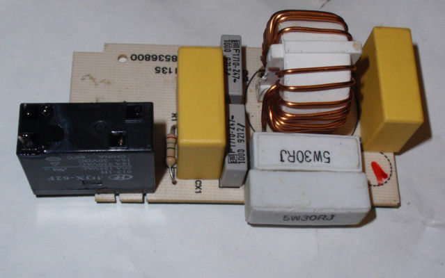
Şebeke gerilimi önce EMI/EMC filtresinden geçirilir. Daha sonra doğrultularak C4 kondansatörü üzerinde filtrelenir.C4'ün kapasitesi yüksek olduğundan ilk enerjilenme sırasında oluşabilecek yüksek kalkış akımını (inrush current) sınırlamak için R2 ve Re1 rölesinden oluşan bir yumuşak başlatma devresi kullanılmıştır.
Röle bobini ve PC güç kaynaklarından (AT/ATX) alınabilecek fan, yardımcı 12 V besleme üzerinden çalıştırılır. Bu 12 V gerilim, 17 V yardımcı beslemeden direnç kullanılarak elde edilir. R1 değeri, röle bobini ve fan üzerinde yaklaşık 12 V oluşacak şekilde seçilmelidir.
Yardımcı besleme devresinde TNY267 kullanılmıştır. Yardımcı beslemenin düşük gerilimde çalışmasını önlemek için R27 ile undervoltage protection (düşük gerilim koruması) sağlanmıştır. Yardımcı besleme, DC bara gerilimi 230 V DC'nin altında olduğunda çalışmaz.
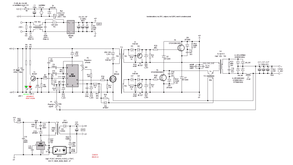
The schamatic of the high power adjustable switching power supply (SMPS) of 3-60V, 40A
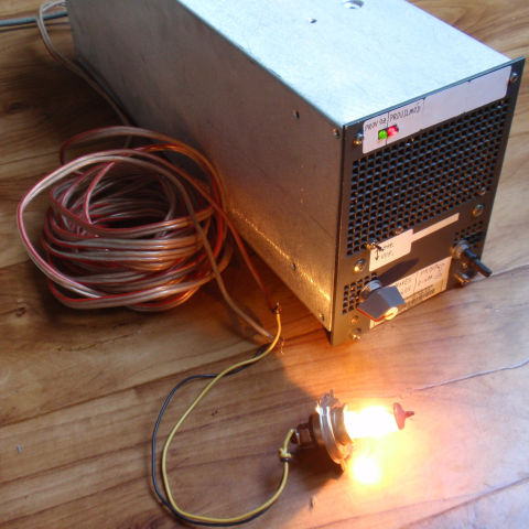
Completed switching power supply
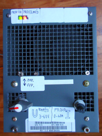
The front panel of the switching power supply - voltage control, current limit control, standby switch S1 and LEDs.
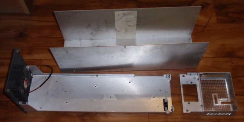
Box from the 56V supply ready for installation of my 3 - 60V supply.
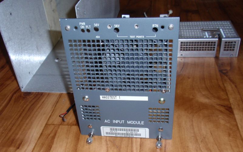
The original front panel
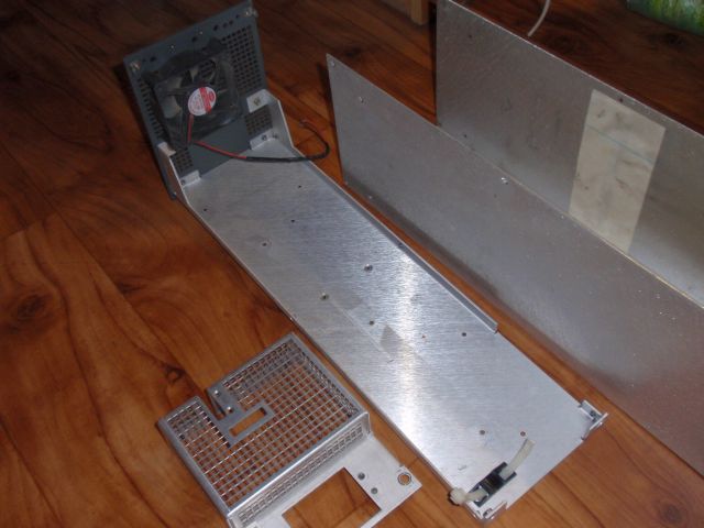
Box with 8cm fan.
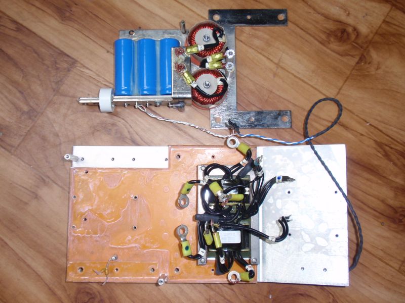
Heatsink, Tr1, L1 and C17 of the old power supply that will be used for construction of my supply.
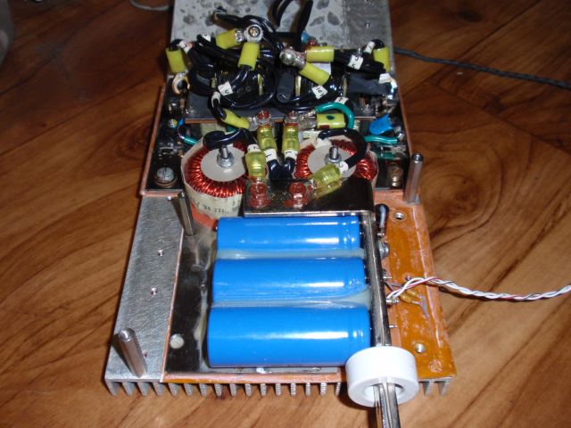
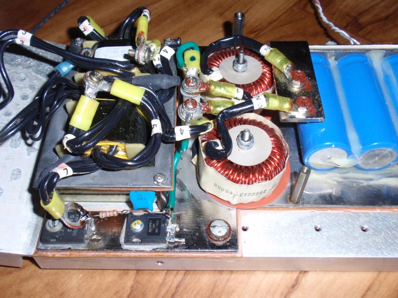
Prepared D5 and D6.
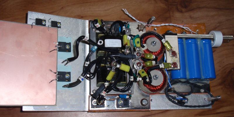
IGBT a reset diodes D7 on heatsink and the board prepared to be dremmeled.
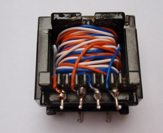
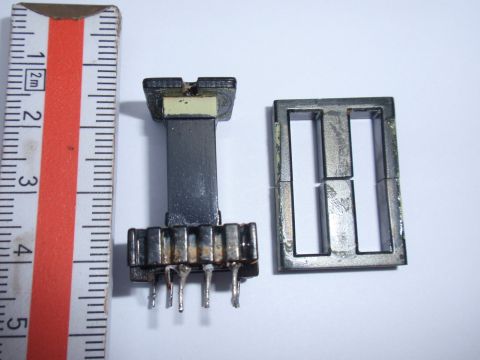
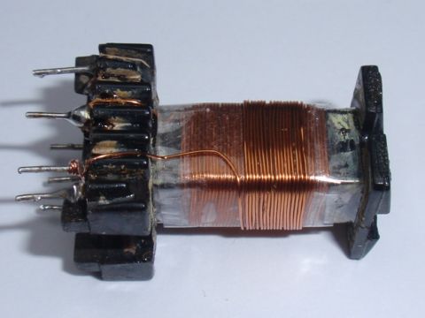
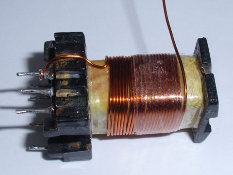
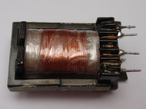
Completed GDT (Gate drive transformer) Tr2.
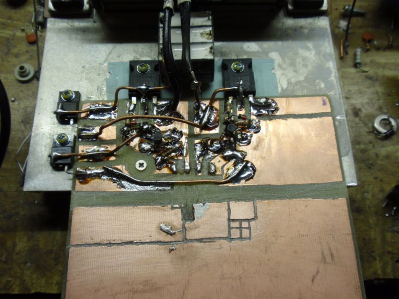
The making of the board begins.
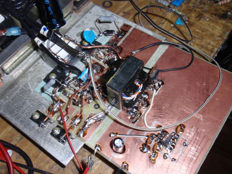
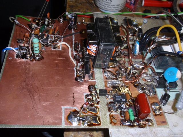
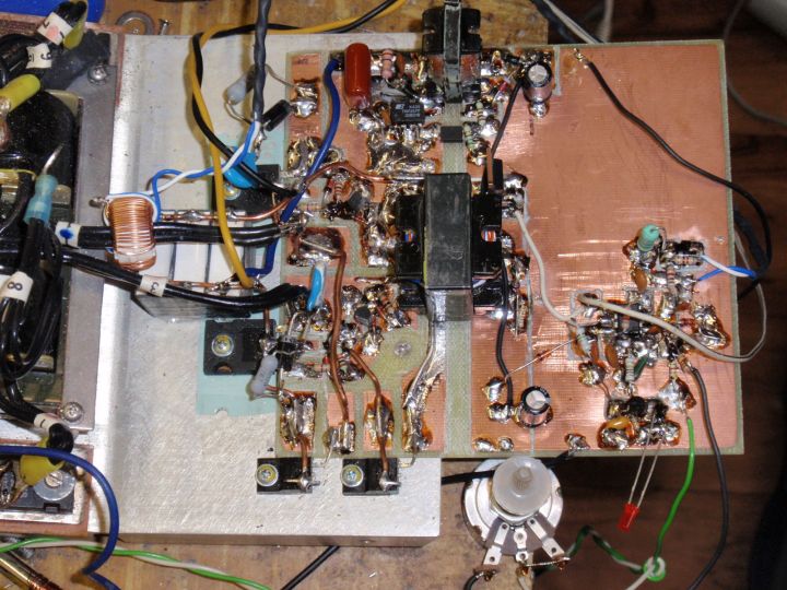
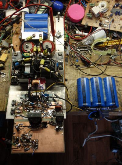
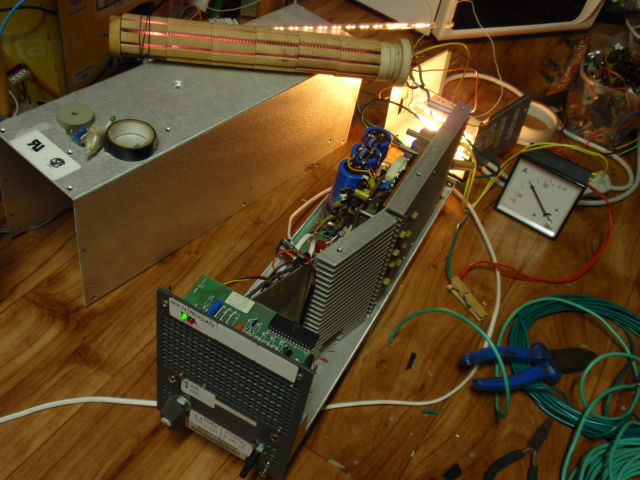
Completed power section, the control circuitry and the Tr2.
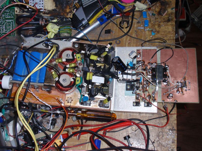
Son düzenleme: