Güncel olmayan bir tarayıcı kullanıyorsunuz. Bunu veya diğer web sitelerini doğru şekilde görüntülemeyebilir.
Yeni sürüme geçmeli veya bir alternatif kullanmalısınız. tarayıcı.
Yeni sürüme geçmeli veya bir alternatif kullanmalısınız. tarayıcı.
Tacho generator
- Konuyu başlatan guclusat
- Başlangıç Tarihi
-
- Etiketler
- tacho generator
Tachometer-and-direction-of-rotation-circuit
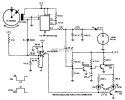
Because of the magnet spacing, a short on pulse is produced by the TL3101 in one direction and a long on pulse in the other direction. A 0-50 JLA meter is used to monitor the flywheel speed while the LEDs indicate the direction of rotation. The direction-of-rotation circuit can be divided into three parts: TLC372 device for input conditioning and reference adjustment. Two 2N2222 transistors which apply the Vee to the two LEDs when needed. The two TIL220 LEDs which indicate clockwise (CW) or counterclockwise (CCW) direction of rotation.

Because of the magnet spacing, a short on pulse is produced by the TL3101 in one direction and a long on pulse in the other direction. A 0-50 JLA meter is used to monitor the flywheel speed while the LEDs indicate the direction of rotation. The direction-of-rotation circuit can be divided into three parts: TLC372 device for input conditioning and reference adjustment. Two 2N2222 transistors which apply the Vee to the two LEDs when needed. The two TIL220 LEDs which indicate clockwise (CW) or counterclockwise (CCW) direction of rotation.
Simple analogue Tachometer
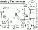
The bridge diode that is connected to the miliamperimeter can be replaced by 4 silicon diodes as the picture shows. The miliamperimeter can be replaced by a multi-meter set to measure mA. To calibrate this circuit first: Adjust R1 and R2 at the middle point. Apply power (12 Volts) and apply 60Hz at the input signal. Adjust R1 until it measures 0.360 (3,600 RPM) Stop the signal (0 hz) and adjust R3 until the meter indicates 0. Apply 60Hz again and adjust R1. If the meter doesn't show "0" at 0Hz and 0.36 at 60Hz, adjust R2 and repeat the calibration.

The bridge diode that is connected to the miliamperimeter can be replaced by 4 silicon diodes as the picture shows. The miliamperimeter can be replaced by a multi-meter set to measure mA. To calibrate this circuit first: Adjust R1 and R2 at the middle point. Apply power (12 Volts) and apply 60Hz at the input signal. Adjust R1 until it measures 0.360 (3,600 RPM) Stop the signal (0 hz) and adjust R3 until the meter indicates 0. Apply 60Hz again and adjust R1. If the meter doesn't show "0" at 0Hz and 0.36 at 60Hz, adjust R2 and repeat the calibration.

