Recently, some of my friends ask me about power supply from 12 V to HV for tube amp, after reading Bob's article about 1626 Auto Darling. I'm thinking of building one vacuum tube amplifier for my brothers new car too. The power of amplifier that suitable for car is around 5W~15W, same as most of the car radio's output power. Some might wanted to install 50W or more in their car but I think its not necessary. We are audiophile that just listen to most natural sound, not blasting out those screws or guts out off the car.
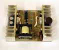
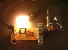
My first design is using ETD29-N27 core from EPCOS, the prototype is proven to drive a set of my 6P3P SE amplifier without any problem. It used only a pair of MTP75N05 MOSFET as power PP stage. I am using TL494 as PWM controller because of its low cost and simple to design. After I had run it for few hours, I change the transformer to larger E36 N67 core to see how's the improvement. The ETD29 heat up a bit when running a 60W bulb and the E36 runs cool.
My first design is using ETD29-N27 core from EPCOS, the prototype is proven to drive a set of my 6P3P SE amplifier without any problem. It used only a pair of MTP75N05 MOSFET as power PP stage. I am using TL494 as PWM controller because of its low cost and simple to design. After I had run it for few hours, I change the transformer to larger E36 N67 core to see how's the improvement. The ETD29 heat up a bit when running a 60W bulb and the E36 runs cool.
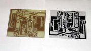
The next day I design a PCB with paralleled MOSFET so that I can drive it to around 150~200W without any problem. I'm stick with ETD29 layout footprint and I can have two version, either for SE or PP type with just the difference of 1 pair/ 2pairs of MOSFET and ETD29 / ETD34 core. The final board measures 10cm X 11cm X 3.5cm. After I had installed all the parts on it and test run it, the performance of this new PCB is bad. MOSFET runs hot and draws current nearly twice higher than the first prototype. I check the schematics and the problem is come from the snubber RC and narrow track width. I mistaken the 0.1 uf as 0.01 uF and harmonics everywhere on the PCB. After I change to 0.1uF the power supply and tin coated the high current track ,it runs happily and only slightly warm, driving a 100W bulb.
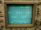
The switching frequency is 48KHz and I had try 80KHz with better result and higher efficiency, but only limited to N67 or N87 type core material. The square wave that I had measure is pure square wave with slight ringing. finetune the snubber circuit will improve a bit. Voltage feedback is important, too little feedback will not regulate the output voltage and too large the feedback will decrease in efficiency, and MOSFET have to handle more current that is actually a waste. Most of the car amplifier using open loop type for best efficiency, I'm apply a little bit of feed back just to compensate the car battery's voltage, from 13~14.4V. When engine is idle, battery voltage is more or less in 12.8~13.5 region and when running high RPM, the alternator will charge the battery and it rises to about 14.4V. Imagine that if I'm not using feedback, when transformer's ratio is 1:26, 13V X 26= 338V and if supply increase to 14.4V, 14.4 X 26= 374.4V ! so what I do is just give a feedback ratio to limit it at 338V. This will not suffer too much from being decreasing the efficiency a little bit.
After this experiments, I build several sets with different output voltage for some of my friends, some are only use a pair of MOSFET for SE amp and some are paralleled pair for PP tube amp. This switch mode power supply need to fine tune for best result every time I build one, I need to work out a more flexible schematics for easier construction and post it here for most of diyers who interested in building one.
Now I'm cracking my head to optimize the single layer PCB layout so that I can release this kit set as soon as possible. The next step is designing the power supply for heater filament, I try to build it as small as possible so that it can be install underneath the chassis. I will post an article about this once the design is completed. Stay tuned.
Eklentiler
Son düzenleme:


