2 channel 100w stereo audio amplifier circuit by STK4231II
If you want to create the 100 watt OCL audio amplifier circuit. I want you to consider this circuit as one. It uses STK4231 IC products to create a simple, small and best economical.
How it works.
The STK4231 is Hybrid IC of Sanyo, in the family of STK4201II. Can provide a high power output to 100 watts per channel. And When connected to the bridge adapter with output altitude of about 400 watts is incredible.
-Built-in muting circuit to cut off various kinds of pop noise.
Greatly reduced heat sink-due to case temperature 125 degrees Celsius.
-Excellent cost performance.
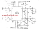
As this circuit, we can design the OCL amplifier 100 watts each channel. Will see that, this circuit consists of only a few external components.
-The capacitor C9,C10 is used to reduce noise at high frequencies.
-The input coupling capacitor are Bolt C1,C11.
The C2,C12 is defined low frequency cut off point that Which can be calculated from the formula : F=1/6.28 C2xR5
Note: two capacitor C2,C12 is defined gain ratio at low frequency but will be must over high Because, while open this circuit will be has a noise “thub…b.b.b” out to your speaker.
– The boost trapping capacitor are C3 and C13. If the value is too low, resulting distortion increases torque at low frequency.
– To reduce oscillation by C5, C8. which reduces the impedance of the power supply circuit to suit the use of IC.
– Setting gain ratio of circuit, which is defined by R5 = 560 and R4=56K will be total gain is VG = 40dB.
If you want to change the rate of expansion, it should change the R5.
The idle current is defied by R21,R22.
The power supply circuit
This our circuit use dual voltage positive – negative 50 volt and current is 5 Amp, we so use power supply as this figure which.
How to build.
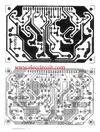
It’s very easy to create, even if you are a beginner. It is important to place the devices correctly follow circuit diagram.
In this figure is PCB and putting position the parts. The IC shouls be hold with the big heat sink.