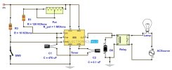
Using simple 555 timer we can design an adjustable timer switch. This circuit is flexible to adjust required time.
Circuit Diagram

Components
Circuit Diagram

Components
- 555 timer
- Electrolytic capacitor – 470 uf
- ceramic capacitor – 0.1nF
- Resistors
- 120k ohm
- 10k ohm
- Relay -12v
- Push button
- Here 555 timer is operated in monostable mode.
- When the trigger input is applied,555 timer produces a pulse. This pulse width depends on R and c values.
- The above proposed circuit is a 1-10 minute timer.When Pot is minimum it gives 1 minute delay,where maximum value of pot can produce 10 minutes.
- Time period can be calculated using formula
- When Pot is maximum R is 120K+1.1M ≈ 1.2M (approximately) and C1=470uf
- For minimum time place the pot in least position.Then R= 120k
- Hence time T=120k*470uf=6 2 seconds~1 minute (approximately).
- A 12v relay is used to drive the ac load connected at the output.
- Thus relay will be on for required amount of time set by the user using pot and then it is switched of automatically.
- This circuit is used in such applications where the load is switched on for sometime and is off for rest of the time.
- To prevent 555 timer from flyback current in the relay use a diode before the relay.
- Some 555 versions may get damaged because of this.
Son düzenleme:
