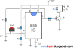
Description:
the above circuit shows how to make a simple latching relay circuit using 555 timer IC, since 555 timer comes with built in flip-flop and comparator circuit. The circuit works as or behave as a toggle switch, the circuit above has two stable states, which are ON and OFF. Once it’s ON, it remains ON forever until you break the circuit or till you press the momentary switch again, to turn it OFF.
This simply means that you have to push once to set the device ON and push again to set the device OFF. This kind of switch works by latching a relay to remain ON state with push of a button and with another push to unlatch the relay. It is working like flip-flop states. In that way you can control power to a device using one momentary push button. The circuit is build around a 555 timer chip which is configured in a way that let it latch on one state and an action is required to change state. The circuit is powered from +5V to +12V DC.
The circuit toggles a relay when momentary switch button S1 is pressed. The operation of this circuit is simple, Pins 6 and 2 of 555 timer chip are at half dc voltage. When pin 3 which is the output is high then capacitor C1 is charged and when it is low capacitor is discharged. When momentary switch is pressed capacitor voltage appears on pin 6 and2 and output pin 3 changes state as well as capacitor voltage changes. So when output (pin 3) is high capacitor has +5V or +12V of dc power. When we press the button again pin 3 goes low and capacitor goes low which is about 0V, when we press button again output goes high again to about +5V or +12V, so we have toggle functionality. When output is high transistor T1 is conducting current and relay is latched ON, when low relay is De-energized. Diode D1 is used to protect transistor from back emf (electromotive force) or reverse voltage generated when relay goes off this diode prevent that from happening since a diode only allows an electrical current to flow on one direction.
You can easily implement this circuit Using this projects to make Remote operated switch, Light operated switch, Clap Switch, GSM based home automation system or something similar.
Parts:
- RL- SPD 12v Relay
- IC- NE555 Timer Chip
- T1-Transistor Bc548 or any similar NPN type
- R1,R2,R3-1k Ohms Resistor
- R4-100 Ohms Resistor
- D1-1N4007 Diode
- C1-1uf Capacitor
- C2-10n Capacitor
- A 12v Battery or a 12v DC Power Source
- SW1-Momentary switch

