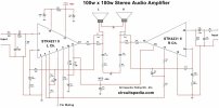
This is a power amplifier based on the (now almost obsolete) STK4192-II stereo power amplifier IC from Sanyo. This amplifier was built to drive my isobaric sub-woofer having a nominal 4Ω impedance (2x 8Ω drivers in parallel), with a power of about 200W.

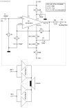
The above schematic shows how two ICs are required to create a bridge-parallel amplifier (BPA). Why would one go about building a BPA (using 4x ICs or 2x stereo ICs) instead of a single discrete amplifier? The reasons can be many including,
- Ease of construction.
- Lower supplies required due to bridge mode operation.
- Greater reliability since each amplifier (of the parallel pair) sees half the load. The load doubling effect of bridging is offset or reversed by paralleling the amplifiers before bridging.
STK4192 is pin-compatible with STK4132 and the schematic is exactly the same as that of 4132 (though I have made changes to a few components, but that is largely due to ready availability of parts, and different gain needed more than anything else). You could simply swap the 4192 for a 4132 and it would still work. With a 4132 the supplies would need to be reduced to +/-20V and power output will be about 20W/channel. In BPA 4132 would give about 80W into 4Ω. Refer to the STK4132 schematicfor details about changes/deviations from the typical application.
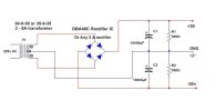
Each amplifier of STK4192 is rated for 50W into 4Ω with supplies of about +/-25V, which can be easily had from an 18-0-18V transformer. For 200W, the transformer needs to be a 250VA unit at the minimum. Since, each STK4192 has two amplifiers, we have 4 amplifiers in total. Thus, when two amplifiers are bridged into 4 ohms, each amplifier sees an equivalent load of 2Ω, but when each "arm" of the bridge is instead a pair of paralleled amplifiers, each amplifier again sees an equivalent load of 4Ω. Thus by using the BPA arrangement we have managed to drive a low impedance/deliver high power whilst remaining within the specification of each amplifier.
In fact this arrangement can be used with any IC power amplifier provided the equivalent load that each amplifier sees is what the amplifier is rated for. Once this is done, we can get a high power amplifier with minimal external parts which results in both reduction in size as well as a modest reduction in cost. The only down-side is that we need at least 4 amplifiers to implement one BPA, which means, for a stereo pair we would need 8 ICs (or 4 stereo ICs). Needless to say, as the load or power handling per amplifier reduces, the no. of individual amplifiers needs to be increased to keep dissipation per amplifier low.
To be noted is the lack of offset nulling and/or high-precision components. The 0.1Ω resistors (R8) at the outputs ensure that any mismatch in the output currents do not result in each amplifier's o/p fighting the other, and the capacitor (C5) ensures that there is no DC interaction between the amplifiers (i.e., no offset at the output). C5 also blocks any DC from getting to the load. This intrinsically provides DC protection to the load, should there be a failure in the amplifier(s).
Despite the general opinion that capacitors in series with speakers are a bad thing, I believe that the pros in terms of reliability far offset the cons, especially given the simplicity of it (no DC protection or offset nulling circuits needed!). Considering the total capacitance that the load sees, we have the equivalent of a 15,000uF cap in series with a 4Ω load - this gives a lower -3dB frequency of about 2.65 Hz. Now, it is a matter of debate as to how long it would take for the capacitance to deteriorate so much that this frequency becomes about 15 or 20 Hz. IMO, it would be long enough that replacing the capacitor(s) would not be a frequent activity, and if it does need replacement its a very easy thing to do - which again makes them worthwhile to have. For the isobaric sub that I built, the drivers are in cone-to-magnet configuration, which means that the inner driver is hidden inside the enclosure - this makes it very difficult to effect repairs should the inner driver get damaged. The output capacitors eliminate the possibility of damage thereby pre-empting the need to ever open up the sub-woofer in the first place!
For the intended purpose, with the specified 4Ω load the amplifier runs very cool. There is no significant increase in heat-sink temperature for normal listening levels, and a (still comfortable to touch) increase in temperature at elevated levels for any period of time. The amplifier is preceded by an equalisation circuit which basically cuts out frequencies over 200 Hz and operates the sub-woofer in the vicinity of its response peak. Due to this, the apparent loading on the amplifier is reduced, thereby reducing dissipation. However for other applications, dissipation may be more (for example in a band-pass or full-range application) but can be expected to be still safe enough.


