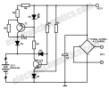
This battery charger circuit can be used to charge one or more batteries with the total nominal voltage of 12 V, meaning ten NiCd battery or six 2 V lead acid. The circuit is pretty small and can be built in a housing network adapter. The incorect usage is impossible: connecting the batteries with reverse polarity, shortcircuit of the output terminals or power loss have no impact on the charger or battery.
We can use a transformer with 18 V on the secondary and then using a diode bridge to rectify the 18V ac voltage we get 22V dc on C1.
The completely discharged batteries are charged at the begining with a 6 mA current thru R2-D2 and R4-R6-D1. One the bat. have reached 0.3 – 0.5 V, the base-emitter voltage of T1 is high enough to bring the transistor in conduction.
Green LED D4 is used as an charging indicator and opens T1.
There is a 60 mA current flowing thru R5-R6, this means that the charging of a 500 mAh NiCd battery will take 12 hours.
If the battery is connected with reversed polarity or there is a shortcircuit, the power transistor T1 remains blocked and the charging current can not exceed 6 – 12 mA. The current draw at maximum load is around 80 mA.
Battery charger circuit schematic

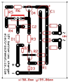
Battery charger PCB Layout


Components List
R1 = R2 = 10K
R3 = 1K
R4 = 5.6K
R5 = R6 = 12Ω
C1 = 1nF
C2 = 220µF / 35V
D1 = 1N4001
D2 = D3 = 1N4148
D4 = green LED
T1 = BD140
T2 = BC546
We can use a transformer with 18 V on the secondary and then using a diode bridge to rectify the 18V ac voltage we get 22V dc on C1.
The completely discharged batteries are charged at the begining with a 6 mA current thru R2-D2 and R4-R6-D1. One the bat. have reached 0.3 – 0.5 V, the base-emitter voltage of T1 is high enough to bring the transistor in conduction.
Green LED D4 is used as an charging indicator and opens T1.
There is a 60 mA current flowing thru R5-R6, this means that the charging of a 500 mAh NiCd battery will take 12 hours.
If the battery is connected with reversed polarity or there is a shortcircuit, the power transistor T1 remains blocked and the charging current can not exceed 6 – 12 mA. The current draw at maximum load is around 80 mA.
Battery charger circuit schematic

Battery charger PCB Layout


Components List
R1 = R2 = 10K
R3 = 1K
R4 = 5.6K
R5 = R6 = 12Ω
C1 = 1nF
C2 = 220µF / 35V
D1 = 1N4001
D2 = D3 = 1N4148
D4 = green LED
T1 = BD140
T2 = BC546
Son düzenleme:
