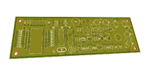
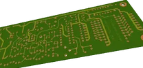
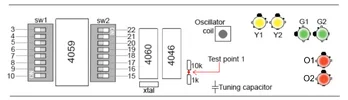
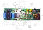
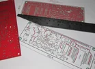
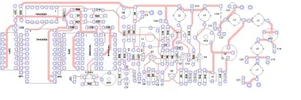
Here's a little overview of a 1Watt FM transmitter driver. Hopefully it will help you with retuning, fault finding or just to learn more about these boards.
The familiar CMOS PLL section has been used in plenty of other designs and seems to work well. Output varies from 500mW to about 1.2W depending on the frequency and the final output device - Motorola 2N4427 always seems to win but at a few quid extra cost of course.
If anyone has more info on this design and where it came from please get in touch. I'm pretty sure i saw a VERY similar PLL and VCO combination and PCB layout in a book i once picked up but i can't be sure.
Component Values for VHF PLL
Resistors
R1 - 10K
R2 - 10K
R3 - 10K
R4 - 10K
R5 - 10K
R6 - 100R
R7 - 1K
R8 - 10K
R9 - 470R
R10 - 10K
R11 - 470R
R12 - 100R
R13 - 470R
R14 - 10K
R15 - 10R
R16 - 47R
R17 - 10R
R18 - 100K
R19 - 1K
R20 - 10K
R21 - 10K
R22 - 1M
R23 - 100K
R24 - 100K
R25 - 100R
RP1 - 9 Pin 100K Commoned Resistor array
RP2 - 9 Pin 100K Commoned Resistor array
Capacitors
C1 - 1uF electrolytic
C2 - 27pF ceramic
C3 - 22pF ceramic (tuning cap- change to extend tuning range)
C4 - 27pF ceramic
C5 - 100pF ceramic (101)
C6 - 100pF ceramic (101)
C7 - 100pF ceramic (101)
C8 - 1000uF electrolytic
C9 - 100nF ceramic (104)
C10 - 100nF ceramic (104)
C11 - 100pF ceramic (101)
C12 - 4.7pF ceramic
C13 - 100nF ceramic (104)
C14 - 100nF ceramic (104)
C15 - 100nF ceramic (104)
C16 - 100nF ceramic (104)
C17 - 100nF ceramic (104)
C18 - 39pF ceramic
C19 - 39pF ceramic
C20 - 39pF ceramic
C21 - 39pF ceramic
C22 - 1nF ceramic (102)
C23 - 10nF ceramic (103)
C24 - 47uF electrolytic
C25 - 1uF electrolytic
C26 - 10uF electrolytic
C27 - 100nF ceramic (104)
C28 - 100nF ceramic (104)
C29 - 100nF ceramic (104)
C30 - 100nF ceramic (104)
C31 - 100pF ceramic (101)
C32 - 100nF ceramic (104)
C33 - 47uF electrolytic
C34 - 100nF ceramic (104)
VC1 - 2..22pF green trimmer
VC2 - 5..60pF yellow trimmer
VC3 - 2..22pF green trimmer
VC4 - 2..22pF green trimmer
Inductors
L1 - Toko tuning coil with screening can 5.5 turns 100-075
L2 - Toko S18 Yellow
L3 - Toko S18 Yellow
L4 - Toko S18 Green
L5 - Toko S18 Green
L6 - Toko S18 Orange
L7 - Toko S18 Orange
L8 - RF choke 10uH-100uH
Semiconductors
VD1 - Variable capacitance diode
VD2 - Variable capacitance diode
VD3 - Variable capacitance diode
D1 - 1N4841
ZD1 -BZX 6.2V Zener Diode
Q1 - BSX20
Q2 - BSX20
Q3 - BSX20 (or ztx313 on older boards)
Q4 - BSX20 (or ztx313 on older boards)
Q5 - 2N4427 with clip on heatsink (Motorola will give more power)
74HC4024 - Binary Counter
74HC4060 - Binary counter with oscillator
74HC4046 - Phase locked loop IC
74HC4059 - Divide by N counter
Miscellaneous
6.4 Mhz Quartz Crystal
DIP1 - 8 Way DIL DIP Switch
DIP2 - 8 Way DIL DIP Switch
PLL FM transmitter driver (aka Dawson driver)
Eklentiler
-
 eagle-pcb-1w-fm.webp88,4 KB · Görüntüleme: 37
 -
 eagle-pcb-transmitter.webp83,3 KB · Görüntüleme: 30
 -
 fm-driver-pll-retuning.webp36,5 KB · Görüntüleme: 28
 -
 fm-transmitter-oscillator-vco-pll-.webp136,6 KB · Görüntüleme: 29
 -
 pll-driver-pcb.webp42,2 KB · Görüntüleme: 29
 -
 PLL-FM-transmitter-pcb.webp56,6 KB · Görüntüleme: 37
Son düzenleme:

