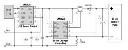
The USB powered battery charger circuit is designed to function as a high-power USB mode. To comply with USB specification (Rev 1.1), a position of great power should not take more than 500 mA from the bus during normal operation. The LM3622 utilizes current limiting resistor R1 0.25 to a maximum of 400 mA of load current. This leaves a surplus of 100 mA that can be used to control circuitry and other features in the USB device.

Li-On USB Powered Battery Charger Circuit Diagram
There are other restrictions in a high-power USB function apply during the startup of the system or as a tool is first connected to an active bus. Until a machine is configured by the USB system, the unit cannot attract more than 100 mA on the bus.
In the drawing above, National Semiconductor LM3525′s USB power switch causes the USB powered battery charger circuit isolated from the bus at boot so that the load current is not to overload the bus. If the port is counted, a USB control signal, the LM3525 switch, connect the USB power (VBUS) on the circuit of the charger. Besides the on-and off-switching, the LM3525 offers current protection and under-voltage design.
When the input voltage of the USB powered battery charger circuit falls to 4.6V and the battery is fully charged from a voltage close to 4.2V, there is a no longer enough voltage on Q1 and D1 to provide a full charge current. With only 400 mV in Q1 and D1, these components are squeezed so that they cannot pass more than 200 mA to the battery.
Available charge current has been reduced by 50% pursuant to low input voltage, extending the time required to “top off” the battery with constant voltage charging.
The battery will not even reach a full charge 4.2V when the input voltage drops below 4.5V. With a USB supply is well designed using a low-impedance connection and cable. However, the voltage at the input to the charging circuit must be sufficiently high that the cost of slow or incomplete mentioned here will not happen.
Thus, the USB powered battery charger circuit presented is able, under most conditions, to take advantage of the USB bus power supplying ability to provide easy and convenient charging Lithium-Ion battery. Please check the LM3622 application notes to obtain clearer information for building a USB powered battery charger.
Son düzenleme:
