Güncel olmayan bir tarayıcı kullanıyorsunuz. Bunu veya diğer web sitelerini doğru şekilde görüntülemeyebilir.
Yeni sürüme geçmeli veya bir alternatif kullanmalısınız. tarayıcı.
Yeni sürüme geçmeli veya bir alternatif kullanmalısınız. tarayıcı.
TDA7293 / TDA7294 amplifikatör devresi
- Konuyu başlatan guclusat
- Başlangıç Tarihi
-
- Etiketler
- amlifikatör tda7293 / tda7294 tda7294
TDA7294 150W Amplifikatör

TDA7294 mikro devresindeki 150W amplifikatör, uzun yıllardır mevcut olmasına rağmen hala büyük ilgi görüyor.
Kullanımıyla oluşturulan güç amplifikatörlerinin bulunabilirliği hakkında sıkça sorulan sorular ve radyo amatörlerinin ilgisi, artan beklentileri karşılaması gereken yeni bir anakartın geliştirilmesine katkıda bulundu. Sunulan köprü amplifikatör, 8 ohm'luk bir hoparlör yükü ile 150 W'lık sürekli bir çıkış sağlar.
TDA7294 mikro devresi, aşırı ısınma ve kısa devre koruma devreleri ile donatılmıştır. Çıkış aşaması, dinamik parametreleri iyileştiren MOS-FET transistörlerinde yapılmıştır. Mikro devrenin MUTE ve ST-BY kapalı girişleri vardır. Bu, örneğin bir mikro denetleyici ile amplifikatörün çalışmasını kontrol etmemize ve güç kaynağını açarken veya kapatırken dalgalanmaları önlememize olanak tanır. Amplifikatörü açmak için ST-BY ve MUTE atlama tellerini 1-2 konumlarına ayarlayın.
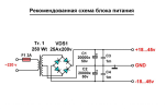
TDA7294'teki 150W amplifikatör, üreticinin teknik belgelerindeki şemaya göre tasarlanmıştır. Amplifikatör devresinin montajı kolaydır, yalnızca birkaç harici bileşen gerektirir. İki bağlı TDA7294 mikro devresinden 150 W çıkış gücü elde etmek için, hareketsiz durumda ± 40V voltaj sağlayacak, tam yükte ± 35V'un altına düşmeyecek kararlı bir güç kaynağı sistemi kullanılmalıdır. Pratikte bu, uygun voltaj ve güce sahip toroidal bir transformatörün yanı sıra önemli kapasitanslı filtreleme kapasitörlerine ihtiyaç olduğu anlamına gelir.
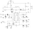
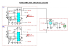
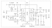
Bir TDA7294 üzerindeki 150W'lık bir amplifikatörün şematik bir diyagramı şekilde gösterilmiştir.

Giriş sinyali "In / GND" konektörüne bağlanmalıdır. Direnç R1 giriş direncini ayarlar. Amplifikatör çıkışı “OUT” konektörüne yönlendirilir. Amplifikatör bir köprü devresinde açılır, bu nedenle çıkışlarından hiçbiri ortak kabloya bağlı değildir.
Kondansatörler C7 ve C8 ilk yük devresinde çalışır, dirençler R3 ... R6 mikro devrenin kazancını ayarlar. C3 ... C6, C11 ve C12 kapasitörleri filtreleyin ve güç kaynağını ayırın. Dirençler R8… R12 ve kapasitörler C9, C10 yumuşak başlatma ve yumuşak kapatma sistemi oluşturur. Açıldıktan sonra, C9 ve C10 kapasitörleri R8 ... R10 dirençleri üzerinden şarj edilir. ST-BY ve MUTE terminallerindeki (pin 9, 10) voltajlar 1,5 V'tan düşük olduğunda devre tamamen devre dışı kalır. ST-BY konektöründeki artan voltaj mikro devreyi açar ve kısa süre sonra MUTE konektöründeki voltajdaki bir artış, bekleme modundan normal çalışmaya geçmesine neden olur.
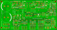
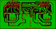
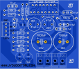
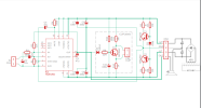
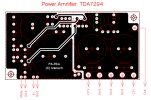
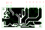
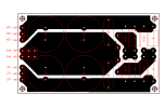
TDA7294 üzerindeki 150W amplifikatör grubunun baskılı devre kartı şekilde gösterilmiştir.

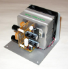
Daha küçük dirençleri ve kapasitörleri lehimleyerek montajı başlatmak en iyisidir. Güç kaynağı kapasitörleri C5, C6, C11 ve C12'yi lehimlemeden önce, TDA7294 mikro devrelerini yalıtım vidaları ve rondelalar kullanarak soğutucuya vidalamanız önerilir. Ardından her iki çipi de lehimleyin.
Modeldeki amplifikatör, 200W'lık bir toroidal transformatör ve iki adet 2×24V alternatif akım sekonder sargısı ile güçlendirildi. Güç kaynağı, 20A ileri akımı olan bir diyot köprüsünden ve 4700 pF / 100 V'luk dört kapasitörden oluşuyordu. 8 ohm'luk bir yükte, amplifikatör sürekli olarak yaklaşık 160W'lık bir çıkış gücü sağladı. Teorik olarak, mikro devrelerin güç kaynağı ve soğutulması için uygun koşullar altında güç ve 200 W alabilirsiniz.
Eki Görüntüle 3224745 Vol ac Voltaj bu devre için çok fazla Entegre Anında gider
Please upload PDF and Gerber alsoTDA7294 150W Amplifikatör

TDA7294 mikro devresindeki 150W amplifikatör, uzun yıllardır mevcut olmasına rağmen hala büyük ilgi görüyor.
Kullanımıyla oluşturulan güç amplifikatörlerinin bulunabilirliği hakkında sıkça sorulan sorular ve radyo amatörlerinin ilgisi, artan beklentileri karşılaması gereken yeni bir anakartın geliştirilmesine katkıda bulundu. Sunulan köprü amplifikatör, 8 ohm'luk bir hoparlör yükü ile 150 W'lık sürekli bir çıkış sağlar.
TDA7294 mikro devresi, aşırı ısınma ve kısa devre koruma devreleri ile donatılmıştır. Çıkış aşaması, dinamik parametreleri iyileştiren MOS-FET transistörlerinde yapılmıştır. Mikro devrenin MUTE ve ST-BY kapalı girişleri vardır. Bu, örneğin bir mikro denetleyici ile amplifikatörün çalışmasını kontrol etmemize ve güç kaynağını açarken veya kapatırken dalgalanmaları önlememize olanak tanır. Amplifikatörü açmak için ST-BY ve MUTE atlama tellerini 1-2 konumlarına ayarlayın.
TDA7294'teki 150W amplifikatör, üreticinin teknik belgelerindeki şemaya göre tasarlanmıştır. Amplifikatör devresinin montajı kolaydır, yalnızca birkaç harici bileşen gerektirir. İki bağlı TDA7294 mikro devresinden 150 W çıkış gücü elde etmek için, hareketsiz durumda ± 40V voltaj sağlayacak, tam yükte ± 35V'un altına düşmeyecek kararlı bir güç kaynağı sistemi kullanılmalıdır. Pratikte bu, uygun voltaj ve güce sahip toroidal bir transformatörün yanı sıra önemli kapasitanslı filtreleme kapasitörlerine ihtiyaç olduğu anlamına gelir.
Bir TDA7294 üzerindeki 150W'lık bir amplifikatörün şematik bir diyagramı şekilde gösterilmiştir.

Giriş sinyali "In / GND" konektörüne bağlanmalıdır. Direnç R1 giriş direncini ayarlar. Amplifikatör çıkışı “OUT” konektörüne yönlendirilir. Amplifikatör bir köprü devresinde açılır, bu nedenle çıkışlarından hiçbiri ortak kabloya bağlı değildir.
Capacitors C7 and C8 work in the first load circuit, resistors R3 ... R6 adjust the gain of the microcircuit. Filter capacitors C3 ... C6, C11 and C12 and disconnect the power supply. Resistors R8… R12 and capacitors C9, C10 form a soft start and soft close system. After switching on, capacitors C9 and C10 are charged through resistors R8 ... R10. The circuit is completely disabled when the voltages at the ST-BY and MUTE terminals (pins 9, 10) are less than 1.5 V. The increased voltage on the ST-BY connector opens the microcircuit, and soon an increase in the voltage on the MUTE connector causes it to switch from standby to normal operation.
The printed circuit board of the 150W amplifier group on the TDA7294 is shown in the figure.

It is best to start the assembly by soldering smaller resistors and capacitors. Before soldering the power supply capacitors C5, C6, C11 and C12, it is recommended to screw the TDA7294 microcircuits to the heatsink using insulating screws and washers. Then solder both chips.
The amplifier in the model is powered by a 200W toroidal transformer and two 2×24V alternating current secondary windings. The power supply consisted of a diode bridge with a forward current of 20A and four capacitors of 4700 pF / 100 V. At an 8 ohm load, the amplifier delivered about 160W of output power continuously. Theoretically, under favorable conditions for power supply and cooling of microcircuits, you can get power and 200 W.

