Güncel olmayan bir tarayıcı kullanıyorsunuz. Bunu veya diğer web sitelerini doğru şekilde görüntülemeyebilir.
Yeni sürüme geçmeli veya bir alternatif kullanmalısınız. tarayıcı.
Yeni sürüme geçmeli veya bir alternatif kullanmalısınız. tarayıcı.
TDA 2030 İle 50 Watt Hi-Fi Çıkış Katı Devresi
- Konuyu başlatan uydudoktoru
- Başlangıç Tarihi
-
- Etiketler
- tda 2030
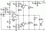
40 Watt Power Amplifier Circuit With TDA2030
Power is 22W into 8 ohm speakers and 40W into 4 ohms. Distortion is 0.012% at 1 kHz / 8 ohm/11W and 0.032% at 1 kHz / 4 ohm/20W. Curent Offers variates IC1 ultimately for the input audio signal, so there will be a similar variation on the R6, R7, R8 and R9. Until the current is close to 1A, voltage resistance is not enough to open the T1 and T2. This means that the performance is less than 2 W into 4 ohm output of the TDA2030. This is a great audio power amplifier, because I know how to create them.
Supply voltage is between 12V and 40V.
Large 40 W mono audio amplifier with built TDA 2030, BD 712 BD 711th


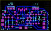
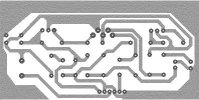
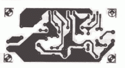
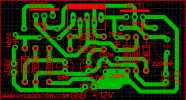
40w power amplifier pcb
Power is 22W into 8 ohm speakers and 40W into 4 ohms. Distortion is 0.012% at 1 kHz / 8 ohm/11W and 0.032% at 1 kHz / 4 ohm/20W. Curent Offers variates IC1 ultimately for the input audio signal, so there will be a similar variation on the R6, R7, R8 and R9. Until the current is close to 1A, voltage resistance is not enough to open the T1 and T2. This means that the performance is less than 2 W into 4 ohm output of the TDA2030. This is a great audio power amplifier, because I know how to create them.
Supply voltage is between 12V and 40V.
Large 40 W mono audio amplifier with built TDA 2030, BD 712 BD 711th


40w power amplifier pcb
Eklentiler
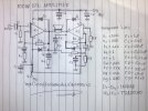
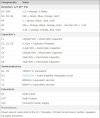
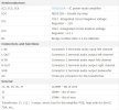
mazeme listesi :
direncler
r1,3,7,9,14 - 22k
r2,8 - 680r
r4,5, 10, 11 - 3,3r/0.5w
r6,12 - 1r
r13 - 1k
kondansatörler
c1,7 - 1uf
c6,12 - 47uf-100uf/40v
c13,14 - 10uf/16v
c2-c5,c8-c11 - 100nf-220nf mkse
transistör
t1,3 - bdx54c
t2,4 - bdx53c
diyotlar
d1-d2-d3-d4 - 1n4002
entegre
us1,2-tda2030
direncler
r1,3,7,9,14 - 22k
r2,8 - 680r
r4,5, 10, 11 - 3,3r/0.5w
r6,12 - 1r
r13 - 1k
kondansatörler
c1,7 - 1uf
c6,12 - 47uf-100uf/40v
c13,14 - 10uf/16v
c2-c5,c8-c11 - 100nf-220nf mkse
transistör
t1,3 - bdx54c
t2,4 - bdx53c
diyotlar
d1-d2-d3-d4 - 1n4002
entegre
us1,2-tda2030
Eklentiler
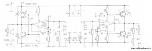
This be Super Bridge 120W Power Amplifier by IC TDA2030 for you like the circuit amplifies that use the integrated circuit. and Transistor BD249 or TIP31 or TIP41 or C1061 and BD250 or TIP32 or TIP42 or A671. It is nice circuit and easy to use.
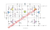
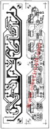
PCB layout and Components layout of 120W supper bridge Power Amplifier using TDA2030
This circuit is designed by using TDA2030A circuit as driver to power transistor output to applied to out up 30 watt.
– then take both circuit to bridge together, makes we have the power output up to 4 times and have even maximum power output is 200Watt.
May don’t be defeated because this circuit give the electric power about 120W that load 2 ohm. When see the circuit will think use important equipment be. Must use power supply source that be appropriate about +15V and -15V that current 2Amp. Besides should use heat sink at have the size is appropriate IC TDA2030 and Q1-Q4 BD249,BD250 for see the circuit has already. Build easy must not fine decorate anything. Request a friend has fun Power Amp Super Bridge 120W by IC TDA2030 please sir.
– The advantage of this circuit, the voltage of the power supply is low (compared to other circuits. Watts are equal in size), so I used the low voltage capacitor, smaller, and cheaper.
– As can be seen from the circuit, we enter a signal input at pin 1 is side single. With pin 1 of IC2 (TDA2030) is connected to ground, And the output signal fed back to the inverting pin (pin 2) of IC2, Allow us to signal with opposite phase, input to the amplifier is one automatically.
How to build
Soldering Electronic Components to the right, onto the PCB as shown in Figure 2. Then install the power transistor to the heat sink. By Vice insulating sheet mica. To prevent a short circuit on the heat sink neatly.
When certain everything must be right, it was the power supply to the circuit, in order to use it, without having to adjust the circuit.
Detail of circuits
Q1,Q3_________BD250___PNP POWER TRANSISTORS(25A,125W)
Q2,Q4__________BD249____NPN POWER TRANSISTORS(25A,125W)
D1,D2,D3,D4____1N4002____Diode 1A 100V
IC1,IC2_________TDA2030A__18W HI-FI AMPLIFIER AND 35W DRIVER
R1,R7,R11,R13__2.2 ohm____Resistors 1/2W
R2,R3,R12______100K______ Resistors 1/4W
R4,R8__________2.2K_______ Resistors 1/4W
R5,R6__________3.3K_______ Resistors 1/4W
R9,R10_________1 ohm______ Resistors 1/2W
C1_____________0.0015uF 50V___ Polyester Capacitor
C2,C3,C4,C5,C7_0.022uF 50V___ Polyester Capacitor
C6_____________10uF 16V_____ Electrolytic Capacitors

PCB layout and Components layout of 120W supper bridge Power Amplifier using TDA2030
This circuit is designed by using TDA2030A circuit as driver to power transistor output to applied to out up 30 watt.
– then take both circuit to bridge together, makes we have the power output up to 4 times and have even maximum power output is 200Watt.
May don’t be defeated because this circuit give the electric power about 120W that load 2 ohm. When see the circuit will think use important equipment be. Must use power supply source that be appropriate about +15V and -15V that current 2Amp. Besides should use heat sink at have the size is appropriate IC TDA2030 and Q1-Q4 BD249,BD250 for see the circuit has already. Build easy must not fine decorate anything. Request a friend has fun Power Amp Super Bridge 120W by IC TDA2030 please sir.
– The advantage of this circuit, the voltage of the power supply is low (compared to other circuits. Watts are equal in size), so I used the low voltage capacitor, smaller, and cheaper.
– As can be seen from the circuit, we enter a signal input at pin 1 is side single. With pin 1 of IC2 (TDA2030) is connected to ground, And the output signal fed back to the inverting pin (pin 2) of IC2, Allow us to signal with opposite phase, input to the amplifier is one automatically.
How to build
Soldering Electronic Components to the right, onto the PCB as shown in Figure 2. Then install the power transistor to the heat sink. By Vice insulating sheet mica. To prevent a short circuit on the heat sink neatly.
When certain everything must be right, it was the power supply to the circuit, in order to use it, without having to adjust the circuit.

Detail of circuits
Q1,Q3_________BD250___PNP POWER TRANSISTORS(25A,125W)
Q2,Q4__________BD249____NPN POWER TRANSISTORS(25A,125W)
D1,D2,D3,D4____1N4002____Diode 1A 100V
IC1,IC2_________TDA2030A__18W HI-FI AMPLIFIER AND 35W DRIVER
R1,R7,R11,R13__2.2 ohm____Resistors 1/2W
R2,R3,R12______100K______ Resistors 1/4W
R4,R8__________2.2K_______ Resistors 1/4W
R5,R6__________3.3K_______ Resistors 1/4W
R9,R10_________1 ohm______ Resistors 1/2W
C1_____________0.0015uF 50V___ Polyester Capacitor
C2,C3,C4,C5,C7_0.022uF 50V___ Polyester Capacitor
C6_____________10uF 16V_____ Electrolytic Capacitors
TDA2030 + transistors BD908/BD907 – 18W HI-FI audio amplifier
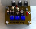
TDA2030 + power transistors (TIP41, TIP42 or 2SC1061, 2SA761 or BD908, BD907 or BD911, BD912 or TIP31, TIP32) for an audio amplifier up to 40 Watts. Simple installation, no special settings requires and uses few components.
The amplifier is based on the TDA2030 IC and two transistors that can be (TIP41, TIP42 or 2SC1061, 2SA761 or BD908, BD907 or BD911, BD912 or TIP31, TIP32), finally you can use several pairs of transistors! The circuit around the TDA2030 is traditional to about 14-20 watts using simple supplies!
The audio output amplified by leaving the pin TDA2030 4, the transistors are active when a large flow of current through R1 and R8 pass transistors to drive and ensure high power output.
Requires a power supply of 18 to 35V/1.5A simple. If you want a version 2 Stereo lot of these!
Eklentiler
-
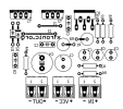 40-watts-amplifier-transistor-TIP142-silk-640x567.png96 KB · Görüntüleme: 92
 -
 203011.jpg104,9 KB · Görüntüleme: 81
 -
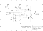 tda2030-40-watts-amplifier-power-transistor.png48,7 KB · Görüntüleme: 84
 -
 tda2030-40-watt-amplifier-transistor-power-pcb-640x567.png83,2 KB · Görüntüleme: 84
 -
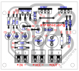 40-watt-amplifier-transistor-TIP142-layout-640x578.png201,4 KB · Görüntüleme: 83
Circuit Power audio Amplifier with TDA2030 2.1 – 3 x 18 Watts
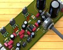
This circuit is a complete application is 2.1 amp, two satellite speakers for TDA2030 and one for the subwoofer, the 2.1 system, widely used in commercial applications as an amplifier for computers, which may give an increased in its audio system with a stereo amplifier + bass amplifier (subwoofer).
Description of the amplifier circuit with TDA 2030
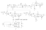
The circuit is divided into 3 parts: power supply, amplifier, stereo amplifier and bass amplifier (subwoofer).
Power supply circuit and pre + low pass filter for the sub power supply
The power supply is of symmetric type, using a transformer, 110 or 220 with dual secondary 12 volts and 3A current. I recommend using a fuse and a switch before the transformer. B1 is a bridge rectifier least 100 volts / 4 A, an example that can be used is GBU606, the filtering circuit is formed of the capacitors C1, C2, C3 and C4, the electrolytes can have values from 4700μF . The power supply for the op amp Highpass filter, is used three terminal integrated circuits 7812 and 7912.
Circuit of the amplifiers of satellite speakers
The left and right channels give exactly the same, let’s see how the left channel: LIN is the audio input jack, which is coupled by C20 to the pot volume adjustment, it is a double pot, and set the two channels simultaneously. R19/C22, helps to improve the signal of the treble. The capacitor C21 couples the signal to CI6 TDA2030, after amplified audio output is pin 4 of integrated. The resistor R7 and R9 are responsible for feedback, so by changing the value of R7 can increase or decrease the gain of the amplifier. R20 and C23 form the compensation network for the speakers.
Circuit pre and Amplifier Subwoofer
The signal comes from the subwoofer to the left and right channels by resistors R15 and R10 being decoupled by capacitor C12, is applied in the operational amplifier 1 IC4A NE5532, which forms a pre-amplifier to boost the signal by 6 times. Determined by R6/R8 resistor.
The components C9, C10 and R10 form a low pass filter in this case is calculated to 200Hz. After leaving IC4B the low frequency audio through the potentiometer P1 that makes the volume level, then forwarded to IC3 is what makes the subwoofer amplifier, the operating principle is the same as satellite amplifiers.

Eklentiler
-
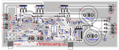 power_amplifier_tda2030_2.1_subwoofer_component_side-640x269.png133,3 KB · Görüntüleme: 80
 -
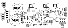 power_amplifier_tda2030_2.1_subwoofer_silk-640x267.png67,3 KB · Görüntüleme: 80
 -
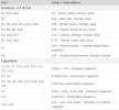 MALZ11.jpg87,3 KB · Görüntüleme: 75
 -
 MALZ12.jpg89,6 KB · Görüntüleme: 66
 -
 MALZ13.jpg75,4 KB · Görüntüleme: 67
 -
 power_amplifier_tda2030_2.1_subwoofer.png47 KB · Görüntüleme: 69
 -
 power_amplifier_tda2030_2.1_subwoofer_pcb-640x267.png46,7 KB · Görüntüleme: 121

