Güncel olmayan bir tarayıcı kullanıyorsunuz. Bunu veya diğer web sitelerini doğru şekilde görüntülemeyebilir.
Yeni sürüme geçmeli veya bir alternatif kullanmalısınız. tarayıcı.
Yeni sürüme geçmeli veya bir alternatif kullanmalısınız. tarayıcı.
SSM2166 Mikrofon Pre Amplifikatörü Devre Şeması
- Konuyu başlatan guclusat
- Başlangıç Tarihi
-
- Etiketler
- mikrofon pre pre amplifikatör ssm2166

Introduction
If you have read the article on the Q&D Compressor available on AMZ and wished there was a way to control more of the parameters, then the Q&D Compressor 2 is the answer. It offers control over the gain, noise gate, and rotation set point, in addition to the compression ratio control offered on the original. This allows more versatility including the ability to use the compressor on line level signals in the studio.
 How It Works
Generally speaking, compression is a method of processing a signal so that the loudest signals are made softer and the most quiet signals are boosted. It is obvious that this reduces the dynamics of the signal but with the advantage of making the output louder to the ear and more quiet since gain can be boosted to raise the signal above the baseline noise floor. Limiting is a little different in that it has an upper level set point. Any signals exceeding this set point are drastically reduced in volume (or limited). This is useful since when the set point is properly adjusted, it is more difficult to overdrive or distort subsequent stages. The SSM2165 and SSM2166 have both compression and limiting integrated onto one chip.
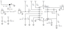
Even with the additional complexity and controls, the Q&D Compressor 2 is almost as simple to build as the original. The brain of the unit is the new Analog Devices SSM2166P chip which has all of the required functions integrated into one 14 pin device. The schematic shows how the functions of the chip have been implemented into a basic compressor for our use.
Since the SSM chip requires 5v DC for proper operation, a 78L05 has been used to provide a clean stable voltage source for the circuit. The power input to the 78L05 can be any 9v or higher dc source, such as a wall wart. Current requirements are quite low (less than 15ma).
The input is buffered by an internal op-amp circuit that drives the voltage controlled amplifier (VCA). A 10uF capacitor (C6) is used to couple the buffer to the VCA. The output of the VCA is low impedance and capable of driving 5k ohm loads at greater than 1v rms. The load on the output is the input resistance (Z) of the next device in the signal chain. As an example, the channel effect return of a Mackie mixer has an input Z of 10k which is higher than the 5k minimum load impedance (higher impedance = less loading) and is compatible with this compressor.
The buffered input of the SSM2166 is also directed through a side chain where it is rectified, filtered and conditioned to control the output level of the VCA. This control signal is rapidly varying the gain of the VCA in order to produce the compression and limiting effects on the input signal. There pins on the chip which allow adjustments to the control circuit for noise gate set point, rotation set point and compression ratio. The gain of the VCA is also adjustable so that a proper output level can be set.
The rectified control signal is filtered by an averaging capacitor (C4) which has been set to 4.7uF in the schematic. This is a good value for most uses however if "pumping" or "breathing" effects are noted in the output signal the capacitance could be increased to reduce these effects. An extra set of pads are provided in parallel to C4 so that another 4.7uF capacitor (or greater) can conveniently be added.
The other controls are the gain control (R10), compression ratio control (R5), noise gate threshold (R7) and rotation point adjustment (R3). A collection of graphs from the 2166 pdf data has been compiled to show how these controls perform and interact.
Building the Compressor
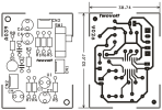
A pc board layout has been provided to make the construction of this project simple. A socket is recommended to hold the SSM chip. Read the Soldering FAQ if you are a beginner at circuit construction.
Testing
Once you have completed the project,it is time to test the circuit. Before applying power, adjust the gain, rotation and compression controls to minimum and the noise gate to mid rotation. With the power on, apply a low level signal and adjust the gain to give a good output level. Then adjust the compression control to the desired amount. There is some interaction between the controls so look at the performance graphs to get and idea of the response.
Schematic for the Q&D Compressor 2
PCB layout and parts placement
Front panel graphic
Performance Characteristics
Parts List
All resistors 1/8w or greater, 5% tolerance
R1,R2 10k
R3 50k linear pot
R4 1k
R6 25k linear pot
R7 1M linear pot
R8,R9 1k
R10 10k audio pot
R12 100k
All capacitors rated greater than input voltage
C1,C3 0.1 uF
C2,C10 1.0 uF
C4 4.7 uF
C5 0.01uF
C6,C7,C8 10.0 uF
C9 33.0 pF
78L05 voltage regulator
SSM2166P Analog Devices compressor chip
case, jacks, wire, solder, etc.
If you are not able to find the SSM2166P chip, I have about 40 that are available on a first-come basis. Use the parts order form to get the address and prices.
Corrections:
If you have had trouble getting the SSM2166 compressor to work, note that pin 12 has to be pulled to ground in order to power up the chip. A jumper has been inserted into the schematic and pcb layout to reflect this. You could replace the jumper with a simple SPST switch in order to have a "mute" switch for the compressor. When the switch is closed the compressor is on and when the switch is open the chip will power down. revised 14 NOV 98
If you have read the article on the Q&D Compressor available on AMZ and wished there was a way to control more of the parameters, then the Q&D Compressor 2 is the answer. It offers control over the gain, noise gate, and rotation set point, in addition to the compression ratio control offered on the original. This allows more versatility including the ability to use the compressor on line level signals in the studio.
Generally speaking, compression is a method of processing a signal so that the loudest signals are made softer and the most quiet signals are boosted. It is obvious that this reduces the dynamics of the signal but with the advantage of making the output louder to the ear and more quiet since gain can be boosted to raise the signal above the baseline noise floor. Limiting is a little different in that it has an upper level set point. Any signals exceeding this set point are drastically reduced in volume (or limited). This is useful since when the set point is properly adjusted, it is more difficult to overdrive or distort subsequent stages. The SSM2165 and SSM2166 have both compression and limiting integrated onto one chip.
Even with the additional complexity and controls, the Q&D Compressor 2 is almost as simple to build as the original. The brain of the unit is the new Analog Devices SSM2166P chip which has all of the required functions integrated into one 14 pin device. The schematic shows how the functions of the chip have been implemented into a basic compressor for our use.
Since the SSM chip requires 5v DC for proper operation, a 78L05 has been used to provide a clean stable voltage source for the circuit. The power input to the 78L05 can be any 9v or higher dc source, such as a wall wart. Current requirements are quite low (less than 15ma).
The input is buffered by an internal op-amp circuit that drives the voltage controlled amplifier (VCA). A 10uF capacitor (C6) is used to couple the buffer to the VCA. The output of the VCA is low impedance and capable of driving 5k ohm loads at greater than 1v rms. The load on the output is the input resistance (Z) of the next device in the signal chain. As an example, the channel effect return of a Mackie mixer has an input Z of 10k which is higher than the 5k minimum load impedance (higher impedance = less loading) and is compatible with this compressor.
The buffered input of the SSM2166 is also directed through a side chain where it is rectified, filtered and conditioned to control the output level of the VCA. This control signal is rapidly varying the gain of the VCA in order to produce the compression and limiting effects on the input signal. There pins on the chip which allow adjustments to the control circuit for noise gate set point, rotation set point and compression ratio. The gain of the VCA is also adjustable so that a proper output level can be set.
The rectified control signal is filtered by an averaging capacitor (C4) which has been set to 4.7uF in the schematic. This is a good value for most uses however if "pumping" or "breathing" effects are noted in the output signal the capacitance could be increased to reduce these effects. An extra set of pads are provided in parallel to C4 so that another 4.7uF capacitor (or greater) can conveniently be added.
The other controls are the gain control (R10), compression ratio control (R5), noise gate threshold (R7) and rotation point adjustment (R3). A collection of graphs from the 2166 pdf data has been compiled to show how these controls perform and interact.
Building the Compressor
A pc board layout has been provided to make the construction of this project simple. A socket is recommended to hold the SSM chip. Read the Soldering FAQ if you are a beginner at circuit construction.
Testing
Once you have completed the project,it is time to test the circuit. Before applying power, adjust the gain, rotation and compression controls to minimum and the noise gate to mid rotation. With the power on, apply a low level signal and adjust the gain to give a good output level. Then adjust the compression control to the desired amount. There is some interaction between the controls so look at the performance graphs to get and idea of the response.
Schematic for the Q&D Compressor 2
PCB layout and parts placement
Front panel graphic
Performance Characteristics
Parts List
All resistors 1/8w or greater, 5% tolerance
R1,R2 10k
R3 50k linear pot
R4 1k
R6 25k linear pot
R7 1M linear pot
R8,R9 1k
R10 10k audio pot
R12 100k
All capacitors rated greater than input voltage
C1,C3 0.1 uF
C2,C10 1.0 uF
C4 4.7 uF
C5 0.01uF
C6,C7,C8 10.0 uF
C9 33.0 pF
78L05 voltage regulator
SSM2166P Analog Devices compressor chip
case, jacks, wire, solder, etc.
If you are not able to find the SSM2166P chip, I have about 40 that are available on a first-come basis. Use the parts order form to get the address and prices.
Corrections:
If you have had trouble getting the SSM2166 compressor to work, note that pin 12 has to be pulled to ground in order to power up the chip. A jumper has been inserted into the schematic and pcb layout to reflect this. You could replace the jumper with a simple SPST switch in order to have a "mute" switch for the compressor. When the switch is closed the compressor is on and when the switch is open the chip will power down. revised 14 NOV 98
Eklentiler
MICROPHONE PRE-AMPLIFIER WITH VARIABLE COMPRESSION AND NOISE GATING PROJECT USING SSM2166
The SSM2166 integrates a complete and flexible solution for conditioning microphone inputs in computer audio systems. It is also excellent for improving vocal clarity in communications and public address systems. A low noise, voltage-controlled amplifier (VCA) provides a gain that is dynamically adjusted by a control loop to maintain a set compression characteristic. The compression ratio is set by a single resistor and can be varied from 1:1 to over 15:1 relative to a user-defined rotation point; signals above the rotation point are limited to prevent overload and to eliminate popping. In the 1:1 compression setting, the SSM2166 can be programmed with a fixed gain of up to 20 dB; this gain is in addition to the variable gain in other compression settings. The input buffer can also be configured for front-end gains of 0 dB to 20 dB. A downward expander (noise gate) prevents amplification of noise or hum. This results in optimized signal levels prior to digitization, thereby eliminating the need for additional gain or attenuation in the digital domain that may add noise or impair accuracy of speech recognition algorithms. The compression ratio and time constants are set externally. A high degree of flexibility is provided by the VCA gain, rotation point, and noise gate adjustment pins.


The SSM2166 integrates a complete and flexible solution for conditioning microphone inputs in computer audio systems. It is also excellent for improving vocal clarity in communications and public address systems. A low noise, voltage-controlled amplifier (VCA) provides a gain that is dynamically adjusted by a control loop to maintain a set compression characteristic. The compression ratio is set by a single resistor and can be varied from 1:1 to over 15:1 relative to a user-defined rotation point; signals above the rotation point are limited to prevent overload and to eliminate popping. In the 1:1 compression setting, the SSM2166 can be programmed with a fixed gain of up to 20 dB; this gain is in addition to the variable gain in other compression settings. The input buffer can also be configured for front-end gains of 0 dB to 20 dB. A downward expander (noise gate) prevents amplification of noise or hum. This results in optimized signal levels prior to digitization, thereby eliminating the need for additional gain or attenuation in the digital domain that may add noise or impair accuracy of speech recognition algorithms. The compression ratio and time constants are set externally. A high degree of flexibility is provided by the VCA gain, rotation point, and noise gate adjustment pins.