SCC3 - 12 Volt 20 Amp Solar Charge Controller
(C) 2009, G. Forrest Cook Introduction
The SCC3 is a solar charge controller, its function is to regulate the power flowing from a photovoltaic panel into a rechargeable battery. It features easy setup with one potentiometer for the float voltage adjustment, an equalize function for periodic overcharging, and automatic temperature compensation for better battery charging over a wide range of temperatures. The SCC3 is able to handle reverse polarity connection of both the battery and photovoltaic panel. The design goals of this circuit were efficiency, simplicity, reliability and the use of field replaceable parts. A medium power solar system can be built with the SCC3, a 12V (nominal) solar panel that is rated from 100 milliamps to 20 amps, and a lead acid or other rechargeable battery that is rated from 500 milliamp hours to 400 amp hours of capacity.
It is important to match the solar panel's current rating to the battery's amp-hour rating (C). A typical maximum battery charging current is C/20, so a 100 amp hour battery should have a solar panel rating of no greater than 5 amps. It is advisable to check the battery manufacturer's data sheets to find the maximum allowable charge current, then choose a PV that does not exceed that value. On the other hand, if the solar panel output current is too low, the battery may never become fully charged.
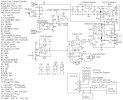
With a few parts changes, the SCC3 circuit can work as a 24V/15A solar charge controller. The 24V parts differences are shown on the schematic.
Basic Specifications (12V version)
Maximum solar charging current: 20 Amps
Nominal battery voltage: 12V
Night time battery current drain: 0.8 - 1.8ma
See the full SCC3 kit specifications for more details.
Here are the SCC3 kit alignment instructions.
Theory
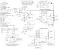
The circuit activation section uses op-amp IC4 wired as a comparator to switch power on for the rest of the SCC3. When the PV voltage is greater than the battery voltage, IC4 turns on and sends power to voltage regulator IC3. Diode D2 prevents damage to IC4 if the battery is connected with reverse polarity. IC3 produces a regulated 5 Volt power source. The 5V is used to power the SCC3 circuitry, it is also used as a reference for the battery float voltage comparator IC1a. The float voltage comparator IC1a compares the battery voltage (divided by R1/VR1 and R3) to the 5V reference voltage (divided by R5 and R6). The comparison point is offset by the thermistor TM1 for temperature compensation. The comparison point is also modified by the Equalize switch, S1 and R2. The output of IC1a goes high (+5V) when the battery voltage is below the float voltage setting. The output goes low when the battery voltage is above the float voltage setting. This provides the charge/idle signal that controls the rest of the circuit.
The charge/idle signal is sent to IC2a and b, a pair of D-type flip-flops. The flip-flops are clocked by the IC1b phase-shift clock oscillator. The clocking causes the flip-flop outputs to produce a square wave charge/idle signal that is synchronized with the frequency of the clock oscillator. The two halves of IC2 operate in synchronization, IC2a is used to drive the PV current switching circuitry, IC2b is used to drive the charging state indicator LED either red (charging) or green (floating).
The clocked charge/idle signal switches bipolar transistor Q1 on and off. The Q1 signal is used to switch power MOSFET Q2, which switches the solar current on and off through the battery. The solar charging current flows through the heavy lines on the schematic. Diode D1 prevents the battery from discharging through the solar panel at night. Fuse F1 prevents excessive battery current from flowing in the event of a short circuit. Transzorb TZ1 absorbs transient voltage spikes that may be caused by lightning.
Use
Connect the solar panel to the SCC3 PV terminals, connect the battery to the SCC3 battery terminals. Put the solar panel in the sun, the battery will charge up. In systems where the battery is frequently deep-discharged, the equalize switch should be occasionally turned on for a period of several hours to a full day. This increases the charge of the battery's weaker cells.
When the battery is low and the sun is shining, the LED will be red. As the battery reaches the float voltage, the LED will quickly alternate red/green. When the sun goes down, the LED will shut off.
SCC3 Circuit Extensions
Secondary Battery Charger
The above circuit may be used if you wish to charge a remote secondary battery. The #1156 lamp limits the secondary battery's charge current to a maximum of 2 amps, it also protects the remote wiring from high currents in the event of a short circuit. The wiring should be rated to handle more than 2 amps of current, #16 or #14 gauge wire is recommended. Other lamps may be used for setting different maximum charge current values. The Schottky diode prevents a load on the main battery from discharging the secondary battery. The diode has a .5V drop, so the secondary battery will always stay .5V below the main battery's maximum (float) voltage setting. A wet cell lead acid main battery and a gell cell secondary battery will work well in this configuration. Float voltages for gell cell batteries are lower than for wet cell batteries.
Dump Load Controller
A Dump Load Controller circuit can be used to feed excess solar power to an auxilliary load such as a heating resistor. The dump load circuit can be constructed from a second SCC3 kit using custom wired jumpers. The dump load circuit monitors the PV voltage. When the PV has charged the battery and the battery reaches the SCC3 float voltage setting, the SCC3 PV circuit opens up and the PV voltage rises. The dump load circuit detects this higher PV voltage and connects the dump load to the PV. For 12V systems, the dump load circuit should be adjusted so that it activates at a PV voltage of around 15V. The dump load resistor should be connected across the terminals labeled "Dump" in the schematic. For the optimal dump load power transfer, the value of the dump load resistor should be chosen so that it pulls the PV voltage down to the PV panel's rated maximum power point during full sun conditions. The dump load resistor should have a power rating that is greater than the PV panel's maximum output wattage rating.
The dump load controller provides a low-quality power source. The power is only available when the main battery becomes fully charged and when it is available, it comes in pulses. Dump load power would be suitable for running a heating resistor or a catalytic electrolyzer for splitting water into hydrogen and oxygen.
Eklentiler
Son düzenleme:


