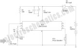
Now you can build your own simple door alarm security system using a tiny microcontroller chip PIC12F635! The circuit is nothing but an aural alert unit, which raises a warning tone when the concerned door is opened by someone. You can install this unit in your front/back door as a security alarm to deter burglars and intruders.
The unit can be powered from four 1.5V AA/AAA cells wired in series (6VDC).
After construction and testing, carefully mount switch S1 in the door (or doorcase) so that it is in open condition when the door is in closed state. Next, set up the alarm unit at a remote location, and make the interconnection between S1 and the alarm unit using low-voltage cables.The Schematic of Door Alarm Circuit

The circuit can be energized by turning the power switch S1 to On position. The Red LED (LED1) blinks 3 times when the power is turned on to indicate that the system has been powered up. Then IC1 (PIC12F635) waits for 30 seconds before it starts monitoring the door sensor (S1) status. This delay is introduced deliberately to help the user to arm the alarm and move out through the door without triggering the alarm system. After this initial delay, when the IC1 detects S1 is closed (door opened) , it drives the iezo speaker (PZ1) with a square wave signal, and the piezo speaker remains on as long as the door is opened. If the door is again closed (and the switch S1 changes to open state) the piezo speaker will not sleep immediately, but still be on for about 10 more seconds but with a slightly different frequency.The firmware is written in C and compiled with MikroC Pro for PIC. Note that MCLR function is disabled, and WDT is OFF in this project. Demo version of MikroC Pro for PIC can be downloded from http://www.mikroe.com
The unit can be powered from four 1.5V AA/AAA cells wired in series (6VDC).
After construction and testing, carefully mount switch S1 in the door (or doorcase) so that it is in open condition when the door is in closed state. Next, set up the alarm unit at a remote location, and make the interconnection between S1 and the alarm unit using low-voltage cables.The Schematic of Door Alarm Circuit

The circuit can be energized by turning the power switch S1 to On position. The Red LED (LED1) blinks 3 times when the power is turned on to indicate that the system has been powered up. Then IC1 (PIC12F635) waits for 30 seconds before it starts monitoring the door sensor (S1) status. This delay is introduced deliberately to help the user to arm the alarm and move out through the door without triggering the alarm system. After this initial delay, when the IC1 detects S1 is closed (door opened) , it drives the iezo speaker (PZ1) with a square wave signal, and the piezo speaker remains on as long as the door is opened. If the door is again closed (and the switch S1 changes to open state) the piezo speaker will not sleep immediately, but still be on for about 10 more seconds but with a slightly different frequency.The firmware is written in C and compiled with MikroC Pro for PIC. Note that MCLR function is disabled, and WDT is OFF in this project. Demo version of MikroC Pro for PIC can be downloded from http://www.mikroe.com
PHP:
/*
  Microcontroller = PIC12F635
  Internal Clock @ 4.0 MHz
*/
sbit Sensor_IP at GP5_bit; // Switch I/P
sbit LED at GP4_bit;       // LED O/P
unsigned short trigger, counter;
void Get_Delay(){
 Delay_ms(300);
}
void main() {
 CMCON0 = 7;
 TRISIO = 0b00101000;  // GP5, 5 I/P's, Rest O/P's
 GPIO = 0;
 Sound_Init(&GPIO,2);
 // Blink LED at Power On
 LED = 1;
 Get_Delay();
 LED = 0;
 Get_Delay();
 LED = 1;
 Get_Delay();
 LED = 0;
 Get_Delay();
 LED = 1;
 Get_Delay();
 LED = 0;
 Delay_ms(30000);
 counter = 0;
 trigger = 0;
 do {
   while (!Sensor_IP) {  // Switch I/P Low
    Sound_Play(3500, 600);
    Delay_ms(500);
    trigger = 1;
    counter = 0;
   }
   if (trigger) {
    Sound_Play(2900, 600);
    Delay_ms(500);
    counter = counter+1;
    if(counter == 10) trigger=0;
   }
 }while(1);
}  // End main()
Eklentiler
Son düzenleme:
