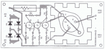
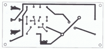
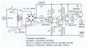
This NiCd baterry charger circuit schematic can charge 6 volts as well as 12 volts NiCad batteries. It uses a transformer which can deliver 4 to 5 A current between 12.6 and 15 V. Ordinary chargers select the charging voltage through a swith but the circuit featured here uses an automatic current regulator.
The charging current is automatically regulated to 4.2 amperes. Once the charging current reaches 4A, the voltage drop at R1 will be 600 mV. In this case the transistor T1 will conduct and supplies current to T2.
Transistor T2 in turn, shorts the base of T3 to ground thereby reducing or totally cytting off the base bias current of T4. The voltage difference between the collector voltage of T4 and the actual charging voltage of the NiCad battery is dissipated by T4. The power dissipation of T4 is therefore the product of the voltage difference and the charging current. In charging 6 volt batteries, the power dissipation can reach up to 40 watts, therefore you must mount T4 with a cooler.
NiCd battery charger circuit diagram
Eklentiler
Son düzenleme:


