How This Circuit works
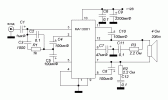
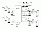
When see a circuit as Figure 1 Many people would doubt that. This circuit will be amplified up to 40 watts. (If as the RMS will is about 17.5 watts at load 4 ohms). You do not insult it because the many circuits that were contained in IC1-HA13001 of Hitachi there. Makes a few external devices, and the output of IC1 that connects to the loud speaker will be connected on the bridge circuit types. So causes the output has a high power there.
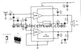
Figure 1 the circuits use IC-HA13001
We do not fear that the speaker will be damaged easily. because in IC1 has the Automatic Shut-Off circuit (ASO) that use to protect the speaker. Thus You need to carefree it. and this circuit will use the power supply range between about 12-18 volts for its’ source.
How to builds this projects
This simple project starting with make the PCB which has copper layout as figure 2 before. Then solder all components as figure 3. We can solder directly the IC1 onto PCB so should take special care.
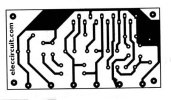
Figure 2 The PCB layout
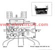
Figure 3 The components layout for PCB
The power supply that can use a DC adapter but must provide current over up 1 amperes. Otherwise, when you accelerate the more volume, the sound will be broken and Adapter will malfunction.
The application this projects
This amplifier project use to amplify from the various sound generator such as The iPad or mobile phone or notebook computer’s etc. Or Modified into the old car stereo that repair difficult. We changed the set to the amplifier.
The detial parts.
The electrolytic capacitors 16 volts
C1_________________1uF
C4, C5, C7, C8_______100uF
C6_________________47uF
C11________________2,200uF
The ceramic capacitors 50V
C2_________________0.001uF
C3, C9, C10__________0.1uF
IC1_number__________HA13001
¼ W + 5% Resistors
R1__________________1K
R2, R3_______________2.2 ohms
Speaker 20 W 4 ohms
Heat sink for IC1
When see a circuit as Figure 1 Many people would doubt that. This circuit will be amplified up to 40 watts. (If as the RMS will is about 17.5 watts at load 4 ohms). You do not insult it because the many circuits that were contained in IC1-HA13001 of Hitachi there. Makes a few external devices, and the output of IC1 that connects to the loud speaker will be connected on the bridge circuit types. So causes the output has a high power there.

Figure 1 the circuits use IC-HA13001
We do not fear that the speaker will be damaged easily. because in IC1 has the Automatic Shut-Off circuit (ASO) that use to protect the speaker. Thus You need to carefree it. and this circuit will use the power supply range between about 12-18 volts for its’ source.
How to builds this projects
This simple project starting with make the PCB which has copper layout as figure 2 before. Then solder all components as figure 3. We can solder directly the IC1 onto PCB so should take special care.

Figure 2 The PCB layout

Figure 3 The components layout for PCB
The power supply that can use a DC adapter but must provide current over up 1 amperes. Otherwise, when you accelerate the more volume, the sound will be broken and Adapter will malfunction.
The application this projects
This amplifier project use to amplify from the various sound generator such as The iPad or mobile phone or notebook computer’s etc. Or Modified into the old car stereo that repair difficult. We changed the set to the amplifier.
The detial parts.
The electrolytic capacitors 16 volts
C1_________________1uF
C4, C5, C7, C8_______100uF
C6_________________47uF
C11________________2,200uF
The ceramic capacitors 50V
C2_________________0.001uF
C3, C9, C10__________0.1uF
IC1_number__________HA13001
¼ W + 5% Resistors
R1__________________1K
R2, R3_______________2.2 ohms
Speaker 20 W 4 ohms
Heat sink for IC1

