LED Blown AC Fuse Indicator Circuit Diagram

uydudoktoru

Tanınmış Üye
Yönetici
Yönetici
PARTS LIST
R1 1MΩ
R2 100Ω
R3 1kΩ
C1 0.47µF 250V
C2 0.47µF 250V
D1 2.7V 0.5W Zener Diode
D2 5.6V 0.5W Zener Diode
D3 LED
Q1 BC547
F1 FUSE

This fuse indicator circuit makes an LED light up if a fuse blows, this gives a quick indication if the fuse has blown and the LED can be sited on the front or rear panel saving time when fault finding.
This blown fuse indicator will work with a wide range of AC supply voltages from 30V to 300V and good for use with few milliampere to many amperes fuse.
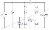
LED-Blown-AC-Fuse-Indicator-Circuit-Diagram.jpg
 

Eklentiler

Son düzenleyen: Moderatör:
Blown Fuse indicator circuit with LED Display

This is a Blown Fuse indicator circuit by LED Display. A Fuse be the equipment protects that use often most. Because of cheapness can use protect electronics expensive circuit. Generally when fuse torn us can know immediately. but in sometimes Fuse torn already we don’t know. such as in electricity automobile system brake system , the system delays the electric current very much, etc. Fuse torn get into trouble at we must know for immediately the safety.
So I would suggest this circuit is simple. It can show with LED that immediately when Fuse blown. See the illustration as Figure 1
In normally or Fuse is good, Current flow through it to D1-diode 1N4148 as forward bias, so cause Q1-PNP transistor do not conduct current, It not work so LED go out.
But Fuse blown or Damaged by high currents from overload, cause open circuit. So there the base current to Q1 it so bias or has higher current flow through R1-resistors, collector, emitter of Q1 and LED1 glow immediately.
by equipment value that show that note for Voltage Source 12V , but if friends want to apply to the level Volt the other.
As a result change value R1 and R2 get by can calculate from R1 = (Vin – 2) x 50 and R2 = (Vin – 2) x 10000/2. Think the work of the circuit has a little, It may help to give friends comfortably up.
blown-fuse-indictor-led-display.jpg

Figure 1 The Blown Fuse indicator LED Display circuit.
How to builds.
This project is not used many components so can assemble on the universal PCB board.as Figure 2 and Figure 3 The wiring and placing components must be carefully for is the polarity of Diodes, LED , transistor BC558 correctly.

Figure 2 Prototype Blown Fuse indicator LED Display.


Geri
Yukarı