Güncel olmayan bir tarayıcı kullanıyorsunuz. Bunu veya diğer web sitelerini doğru şekilde görüntülemeyebilir.
Yeni sürüme geçmeli veya bir alternatif kullanmalısınız. tarayıcı.
Yeni sürüme geçmeli veya bir alternatif kullanmalısınız. tarayıcı.
Elektronik yük devresi
- Konuyu başlatan guclusat
- Başlangıç Tarihi
-
- Etiketler
- elektronik yük elektronik yük devresi
Dummy load

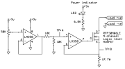
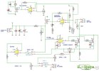
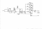
Schematic:

I didn't bother with a load read-out like Dave did. All you need to do is clip a multimeter across the big current sense resistor, and as it is 1 Ohm, then 100 mV on the meter will represent 100 mA current.
It seems to work pretty well. I could only get the lower limit down to around 20 mA but the op-amp wasn't a rail-to-rail one. The pot is a 10-turn wirewound, which gave reasonably sensitive control.

Schematic:

I didn't bother with a load read-out like Dave did. All you need to do is clip a multimeter across the big current sense resistor, and as it is 1 Ohm, then 100 mV on the meter will represent 100 mA current.
It seems to work pretty well. I could only get the lower limit down to around 20 mA but the op-amp wasn't a rail-to-rail one. The pot is a 10-turn wirewound, which gave reasonably sensitive control.
Eklentiler
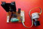
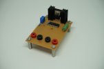
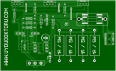
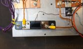
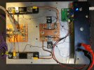
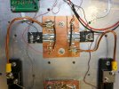
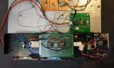
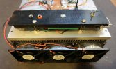
So I was in need of a small dummy load that can handle a few watts to test a small SMPS. I couldn’t wait until the holidays and the following weekend were over so I had to improvise something using components I had laying around. As I stopped etching my own PCBs at home I had to go old-school and build everything using a prototyping board. I’m quite happy with how the result turned out.
The circuit is very common and nothing special at all. The core of the circuit is a MosFET which is deliberately held in a semi-conductive state. A 10-turn potentiometer and a couple of OpAmps are used to control the gate voltage and therefore the current flowing through this dummy load. The shunt resistor R6 should probably be lower to decrease the voltage drop across the dummy load but I only had 1 ohm power resistors lying around. However, the nice benefit of this is that the voltage drop across the resistor doesn’t need to be converted to retrieve the current going through the load.
Note that this is a purely resistive DC dummy load. Furthermore, this load may not be used for AC signals due to the fact that we’re using a MosFET which only works in one direction.
I didn’t have a through-hole voltage regulator around for the +5V rail of the OpAmps so I had to put some SMD components on the solder-side of the prototyping board.
One of the 4mm connector pairs is for the power supply, the other pair is to connect the load itself.
For what I needed it this little device performed very well. I don’t really have needs for a professional dummy load but I might create a second version of this one with a proper enclosure at some point. Maybe even a fancy touchscreen?
Eklentiler
Son düzenleme:
AYARLI ELEKTRONİK YÜK DEVRESİ,
Eklentiler
-
 nagruzka_tok_skhema_500-5.jpg124,4 KB · Görüntüleme: 26
 -
 nagruzka_tok_skhema_500-1.jpg88,3 KB · Görüntüleme: 24
 -
 nagruzka_tok_skhema_500-4.jpg154,7 KB · Görüntüleme: 20
 -
 nagruzka_tok_skhema_500-6.jpg140,8 KB · Görüntüleme: 21
 -
 nagruzka_tok_skhema_500-2.jpg115,1 KB · Görüntüleme: 18
 -
 nagruzka_tok_skhema_500-3.jpg103,7 KB · Görüntüleme: 19
Güç kaynağı için elektronik yük.
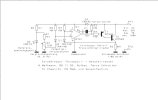
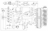
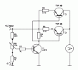
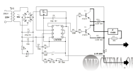
Nikrom spiralleri, yüksek güçlü dirençler, otomotiv halojenleri vb. Güç kaynaklarını test ederken size pes etmenizi sağlayacak elektronik bir yük sunuyoruz. Herkese, 0 ila 20 A arasında (eğer istenirse ve üstü) yumuşak bir ayarlama vardır.


Tasarım, içinde mevcut bir fan bulunan bir bilgisayar güç kaynağı durumunda yapılır (devrenin monte edildiği radyatörü soğutmak için). Kullandığım radyatör bir bilgisayar işlemcisinden. Tasarımın güç transistörleri, almak istediğiniz maksimum yük akımına bağlı olarak seçilir, şöntlü ölçüm kafası seçilir.
Test edilen güç kaynağı ünitesi el'in giriş terminallerine bağlanır. yük ve direnç R6 istenen akımı göstermiştir.
Nikrom spiralleri, yüksek güçlü dirençler, otomotiv halojenleri vb. Güç kaynaklarını test ederken size pes etmenizi sağlayacak elektronik bir yük sunuyoruz. Herkese, 0 ila 20 A arasında (eğer istenirse ve üstü) yumuşak bir ayarlama vardır.


Tasarım, içinde mevcut bir fan bulunan bir bilgisayar güç kaynağı durumunda yapılır (devrenin monte edildiği radyatörü soğutmak için). Kullandığım radyatör bir bilgisayar işlemcisinden. Tasarımın güç transistörleri, almak istediğiniz maksimum yük akımına bağlı olarak seçilir, şöntlü ölçüm kafası seçilir.
Test edilen güç kaynağı ünitesi el'in giriş terminallerine bağlanır. yük ve direnç R6 istenen akımı göstermiştir.
Eklentiler
Most occasions in electronics call for a voltage source set to a specific value. However, there are some situations which are more concerned about how many electrons are flowing as opposed to the voltage, and this is what a constant current source does! These are useful for laser and electroplating applications.
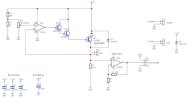
How Does the Power Supply Circuit Work?
Voltage causes a current, not the other way around! So to make a device that provides a constant current no matter the load, we have to use negative feedback and convert the current flowing through our load into a voltage. Luckily, there is a very easy way to convert a current to a voltage which involves using a small ohm resistor (in our case, a 0.1-ohm resistor). The voltage across this resistor will be proportional to the current (thanks to V = IR) and using that, we can fix the current through the circuit. The voltage across the resistor is fed into the negative input of an op-amp and a fixed known voltage is fed into the positive terminal. The output of the op-amp is connected to the base of a power transistor (ignoring the Darlington pair) which controls how much current can flow through the circuit. The op-amp in this circuit (U1A) is in a closed loop because the negative input and output are connected together (through Q3) and so the op-amp will “attempt” to keep the + and – terminals at the same voltage potential.
The best way to see how this circuit works is an example:
We want to set our constant current source to 1 amp and we have connected a load of 1 ohm across the output. If 1 amp flows through the circuit, then we should expect to see a voltage of 0.1V across the 0.1-ohm resistor and so, therefore, we tune the potentiometer such that a voltage of 0.1V is fed into the positive terminal of U1A.
If the current going through the load is lower than 1 amp then the voltage across the 0.1 ohm resistor will be less than 0.1V and this is seen at the negative terminal at U1A. Because the positive terminal is larger than the negative terminal the op-amp will become more positive and therefore increase the conduction of Q3. This increase in conduction of Q3 allows more current to flow through the load and the 0.1-ohm resistor. If the current flowing through the resistor goes beyond 1 amp, then the voltage across the 0.1ohm resistor becomes greater than 0.1V. This means that the negative input to the op amp U1A becomes bigger than the positive input, and therefore the op-amp becomes more negative. This reduction in output voltage results in the conduction of Q3 being reduced and thus conducts less. This reduces the current flowing through the load and therefore the 0.1ohm resistor.
To help see what the current flowing through the load is, a voltage meter is connected to an amplifier (U1B). The job of the amplifier is to amplify the voltage across the 0.1ohm resistor to a readable level for a cheap LED digital display. D1 is used to prevent EMF spikes that may be created by loads from damaging the transistor Q3. The transistor Q3 should be in a TO-3 case with some form of heat dissipation for currents over 100mA and should have both a heatsink and an additional fan for current above 1A.

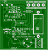
PCB layout for the constant current source
Required Materials
| Component | Schematic Reference | Quantity
| 10K Resistor | R1, R4 | 2
| 1K Resistor | R2, R5 | 2
| 0.1 Resistor (Power Metal Film) | R3 | 1
| 100nF Capacitor | C2, C3, C4 | 3
| 470uF Capacitor | C1 | 1
| 1N4148 Signal Diode | D1, D2 | 2
| LM358 | U1 | 1
| 8 DIP Socket | U1 | 1
| 100K Linear Potentiometer | RV1 | 1
| 2N3904 Transistor | Q1, Q2 | 2
| 2N3055 | Q3 | 1
| Digital LED Voltmeter | P4 | 1
Constructing the Constant Current Source
For this project, the circuit is powered by an old computer PSU (ATX) as these units can provide a substantial amount of current at low voltages. The constant current source currently does not have a dedicated case but instead uses an open style to demonstrate the construction. This circuit, despite outputting large currents, uses very low voltages (less than 12V) so this circuit is very safe (unlike mains-powered projects).

Circuit before wired up

Side view of test constant current source

Wiring to front panel

TO-3 mounting and fan assisted cooling


How Does the Power Supply Circuit Work?
Voltage causes a current, not the other way around! So to make a device that provides a constant current no matter the load, we have to use negative feedback and convert the current flowing through our load into a voltage. Luckily, there is a very easy way to convert a current to a voltage which involves using a small ohm resistor (in our case, a 0.1-ohm resistor). The voltage across this resistor will be proportional to the current (thanks to V = IR) and using that, we can fix the current through the circuit. The voltage across the resistor is fed into the negative input of an op-amp and a fixed known voltage is fed into the positive terminal. The output of the op-amp is connected to the base of a power transistor (ignoring the Darlington pair) which controls how much current can flow through the circuit. The op-amp in this circuit (U1A) is in a closed loop because the negative input and output are connected together (through Q3) and so the op-amp will “attempt” to keep the + and – terminals at the same voltage potential.
The best way to see how this circuit works is an example:
We want to set our constant current source to 1 amp and we have connected a load of 1 ohm across the output. If 1 amp flows through the circuit, then we should expect to see a voltage of 0.1V across the 0.1-ohm resistor and so, therefore, we tune the potentiometer such that a voltage of 0.1V is fed into the positive terminal of U1A.
If the current going through the load is lower than 1 amp then the voltage across the 0.1 ohm resistor will be less than 0.1V and this is seen at the negative terminal at U1A. Because the positive terminal is larger than the negative terminal the op-amp will become more positive and therefore increase the conduction of Q3. This increase in conduction of Q3 allows more current to flow through the load and the 0.1-ohm resistor. If the current flowing through the resistor goes beyond 1 amp, then the voltage across the 0.1ohm resistor becomes greater than 0.1V. This means that the negative input to the op amp U1A becomes bigger than the positive input, and therefore the op-amp becomes more negative. This reduction in output voltage results in the conduction of Q3 being reduced and thus conducts less. This reduces the current flowing through the load and therefore the 0.1ohm resistor.
To help see what the current flowing through the load is, a voltage meter is connected to an amplifier (U1B). The job of the amplifier is to amplify the voltage across the 0.1ohm resistor to a readable level for a cheap LED digital display. D1 is used to prevent EMF spikes that may be created by loads from damaging the transistor Q3. The transistor Q3 should be in a TO-3 case with some form of heat dissipation for currents over 100mA and should have both a heatsink and an additional fan for current above 1A.

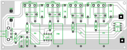
PCB layout for the constant current source
Required Materials
| Component | Schematic Reference | Quantity
| 10K Resistor | R1, R4 | 2
| 1K Resistor | R2, R5 | 2
| 0.1 Resistor (Power Metal Film) | R3 | 1
| 100nF Capacitor | C2, C3, C4 | 3
| 470uF Capacitor | C1 | 1
| 1N4148 Signal Diode | D1, D2 | 2
| LM358 | U1 | 1
| 8 DIP Socket | U1 | 1
| 100K Linear Potentiometer | RV1 | 1
| 2N3904 Transistor | Q1, Q2 | 2
| 2N3055 | Q3 | 1
| Digital LED Voltmeter | P4 | 1
Constructing the Constant Current Source
For this project, the circuit is powered by an old computer PSU (ATX) as these units can provide a substantial amount of current at low voltages. The constant current source currently does not have a dedicated case but instead uses an open style to demonstrate the construction. This circuit, despite outputting large currents, uses very low voltages (less than 12V) so this circuit is very safe (unlike mains-powered projects).

Circuit before wired up

Side view of test constant current source

Wiring to front panel

TO-3 mounting and fan assisted cooling

Son düzenleme:
Elektronik yük
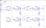
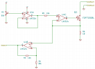
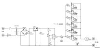
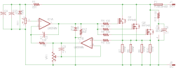
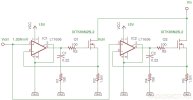
Mosfet-transistörlerdeki elektronik yük eşdeğerinin şematik diyagramı
Elektronik yük eşdeğerinin teknik özellikleri:
Akım tipi - direkt ;
Maksimum çalışma voltajı - 70 V ;
Akım ayar aralığı - 900 mA - 15 A ;
Devre için kendi güç kaynağı - 12 V, 10 mA
Bir yük direnci olarak, burada R6, R10, R7, R11 kaynak devresinde güçlü dirençlere sahip dört paralel mosfet transistör VT1-VT4 IRFP260N kanalı kullanılır . Bu dirençler akım sensörleri olarak kullanılır. VT1-VT4 kapıları, iki DA1, DA2 LM358 mikro devresinden oluşan dört özdeş işlemsel amplifikatör tarafından kontrol edilir . Doğrudan girişleri, akımı fiilen düzenleyen ( VT1-VT4 kanallarının iletkenliğini değiştiren ) bölücü R1R2R3'ten gelen voltajla beslenir ve evirici girişler , R6, R10, R7, R11 akım sensörlerinden voltaj alır .
Düzenleme ilkesi şu şekilde gerçekleştirilir: işlemsel yükselteçlerin çıkışlarındaki değerler, ters çevirme ve doğrudan girişlerindeki voltaj değerlerinin eşitliğini sağlayacak şekilde değişecektir. Doğrudan girişlerdeki voltaj değişmez - bizim ayarımız değişken bir direnç R3 kullanıyor . İşlemsel yükselticinin çıkışındaki voltaj değişir - kontrollü transistörün kanalının direnci değişir - akım sensörlerindeki voltaj, opampların doğrudan girişlerinde ayarlanan voltaja ayarlanır. Böyle bir yük kuklasının önemli bir avantajı, içinden geçen akımın uygulanan voltajdan bağımsız olmasıdır. Onlar. limiti 10 A olarak ayarlarsanız, bu değer 10 V'luk bir voltaj ve 70 V'luk bir voltaj için aynı kalacaktır.
Teknik özelliklerde, 15 A'lık bir üst akım sınırı belirtmiştim - bu, belirtilen bileşen değerleri ile bu devreden çıkarılabilecek maksimum değerdir. Ancak bu tür akımların genellikle aşırı olduğu ortaya çıkar ve üst sınırı azaltmak için R1 direncinin direncini artırmak yeterlidir . Maksimum akımın farklı değerleri için bu direncin bazı direnç değerlerini vereceğim: 91 kOhm - 5 A, 68 kOhm - 7 A, 47 kOhm - 10 A.

