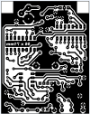
This project came about because I wanted to roll my own reverb. A common way to do this is to use a tapped delay line, but no such chips exist any more. No matter; the result is the same as using multiple delay lines in series and/or parallel. Several DIY reverb effects use the excellent accutronics Belton Digi-Log reverb module, and the associated patent, US8204240, shows that it uses three PT2399 delay chips, one of which is modulated at a slow rate to give a more realistic spring reverb sound. The Accutronics module is not commonly avalable in Britain (also it's cheating to use a ready made effect module!), but I did have a tube full of PT2399s (I absolutely love these chips). I also wondered whether just two could do the job, and it turns out that for guitar use you can indeed get a primitive but usable effect this way. I think this makes the Equinox II the simplest DIY reverb project on the net at the moment!
In the Equinox II the reverb effect is acheived by passing the audio through two delay lines in parallel. One is arranged for a short delay (about 80ms), and the other a long delay (about 250ms). The outputs from each are summed and fed back to the input of the delay lines, and also mixed with the original audio via a mix pot- that's it. (I have an affection for one-knob effects.)
 In detail, after passing through the input buffer the guitar signal is sent both to the output mixer and to the JFET analog switch. This switch allows the input to the delay line to be muted, creating bypass with tails (this is exactly the same as my Small Time delay).
Following the JFET the signal then passes through a 15nF capacitor which provides a little bass cut, to stop the reverb getting too muddy, and it then feeds into a second-order high-cut filter. This is also where the output of the delays lines is fed back in.
The output of this filter feeds the short delay line, and also the long delay line (via an unavoidable inverting buffer).
After the signals emerge from the two delay lines they are both summed and filtered again. All this filtering is necessary to reduce noise from the analog-digital-analog conversion inside the ICs.
I spent a long time tweaking the delay times, filtering, feedback, and mixing ratios, to get what I think is the most usable reverb sound using standard component values and the simplest architecture. My first Equinox prototype also had adjustable delay time on the long delay line, and a fat/bright switch. But I didn't find these to be very useful (at anything but the optimum delay time all you get are 'metallic bathroom' type sounds), so I trimmed the circuit down to the bare essentials, creating the Equinox II shown here.

Technical details:
Input impedance = 1M ohms
Output impedance = 100 ohms
Current consumption = 38mA when active. (Like all delay effects it is fairly current hungry, so there is not much point making it battery powered.)
You will find the schematic, layouts and BOM here (340kB).
Note: If you print the PCB layout make sure your printer settings are set to "zero page scaling".
In the Equinox II the reverb effect is acheived by passing the audio through two delay lines in parallel. One is arranged for a short delay (about 80ms), and the other a long delay (about 250ms). The outputs from each are summed and fed back to the input of the delay lines, and also mixed with the original audio via a mix pot- that's it. (I have an affection for one-knob effects.)

Following the JFET the signal then passes through a 15nF capacitor which provides a little bass cut, to stop the reverb getting too muddy, and it then feeds into a second-order high-cut filter. This is also where the output of the delays lines is fed back in.
The output of this filter feeds the short delay line, and also the long delay line (via an unavoidable inverting buffer).
After the signals emerge from the two delay lines they are both summed and filtered again. All this filtering is necessary to reduce noise from the analog-digital-analog conversion inside the ICs.
I spent a long time tweaking the delay times, filtering, feedback, and mixing ratios, to get what I think is the most usable reverb sound using standard component values and the simplest architecture. My first Equinox prototype also had adjustable delay time on the long delay line, and a fat/bright switch. But I didn't find these to be very useful (at anything but the optimum delay time all you get are 'metallic bathroom' type sounds), so I trimmed the circuit down to the bare essentials, creating the Equinox II shown here.

Technical details:
Input impedance = 1M ohms
Output impedance = 100 ohms
Current consumption = 38mA when active. (Like all delay effects it is fairly current hungry, so there is not much point making it battery powered.)
You will find the schematic, layouts and BOM here (340kB).
Note: If you print the PCB layout make sure your printer settings are set to "zero page scaling".
Eklentiler
Son düzenleme:

