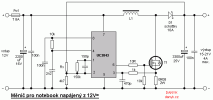
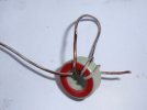
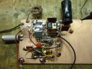
Often it is necessary to power the notebook / laptop in places where AC mains power is not available, but only 12V DC power supply, eg battery, car battery, onboard network of the vehicle or solar cells. It would be inefficient and unnecessarily complicatedt to construct converter from 12V to mains (230V/50Hz), which would then feed the switching supply of notebook, again creating a small DC voltage. Therefore, it is preferable to use direct DC / DC converter that adjusts the voltage in a single step. Power supply voltage of various notebooks may vary, but is usually in the range of 15 to 21V. The output voltage is always higher than the input, and therefore step up (boost) topology was chosen. The circuit can also be used for other purposes than powering the notebook. You can use it as an inverter 12V / 24V for 24V appliances from the 12V power supply or 12V battery. The control circuit is UC3842, that is simmilar to the well known UC3842, but with lower UVLO, which starts working at 8.5 V. As the switching element serves the low-voltage MOSFET N. It can be any type of voltage Uds 30-60V. The on state resistance should not be higher than 6mR and switching times better under 100ns. Yoz can used SMD types 06N03LA, FDB6670AL or N306AS, which can be obtained from PC motherboards. IRF2804S is also suitable. SMD transistors does not need a heatsink, only cooling pad on the PCB, because the loss is low due to the low on resistance. Can also be used with conventional through hole transistor case, for example IRF3205 and IRF1405. In the through hole transistors, on resistance is not so critical, because they can be screwed to the heat sink. Because the operating voltage is low, D1 can be Schottky with low voltage drop. Loss on it is at full load about 2W and requires little heatsink, to which it is screwed or soldered. I used type SBL1040CT (10A, 40V) from ATX PC power supply. L1 has at least 15 turns of 1mm diameter wire and is wound on the iron powder ring obtained also from motherboard. The ring is green-red (permeability 55), has an outer diameter of 16 mm, inner diameter of 8 mm and a height of 6 mm. You can also use yellow-white or green-blue ring eg from AT or ATX (both the permeability of 75). Higher permeability achieves the same inductance with fewer turns. Too few turns may result in excessive heating of the core. The minimum input voltage of the inverter is 8.5 V, the maximum input voltage is equal to the output voltage. The output voltage is determined by resistor Rx. It is calculated by the formula:
Rx = (U [SUB]OUT[/SUB] - 2.5) . 1880Eg. for the output voltage of 20V it is around 33k and 31k for 19V. Select the output voltage according to your laptop. Switching frequency is around 80kHz. The maximum load is 4A. The efficiency is higher than 90%. Boost (step up) inverter disadvantage is that ot (without the addition of other active power components) can not be protected against overload or short circuit. In this case the Po1 fuse will blow. Even after closing the T1 the current can flow from input through L1 and D1 to output. If it bothers you, you can use this converter . Inductance of L1 is 60 - 240uH. Larger inductance does not make sense because of the unnecessarily large size and DC resistance. With smaller inductance excessive ripple current flowing through it, and makes unnecessary stress on the components. If too small a number of turns (too much voltage per turn) may also make the iron core overheat.
It is necessary to use a proper fuse. I am not responsible for any of your damage caused by this device.

Eklentiler
Son düzenleme:


