Quartz Crystal Oscillator – Overview
Quartz crystal oscillatoris a stable frequency generator using a Quartz Crystal as a resonator. In the crystal oscillator circuit, frequency stability is one of the most important references, which is a factor in the ability of various load conditions to provide a constant output frequency.
Quartz crystal oscillatorused in Quartz Crystal is very small and thin section, or a quartz wafer is cut with two parallel surfaces metallised to create the necessary electrical connections. End of the oscillation frequency is strongly influenced by the physical size and thickness of a piece of quartz crystal. So it is a very important parameter to be strictly controlled and known as the “characteristic frequency” of the crystal. Alternatively, in other words, the size and shape determine the frequency or crystal cannot be used on any other frequency.
Quartz Crystal Oscillator
The uses of quartz crystal oscillators are intended to reduce or even eliminate the lowest levels of the factors that can affect the frequency stability. The factors that most often appear to affect the output frequency stability, among others, variations in load, temperature, and the change in DC power supply. Selections of the proper components are used in a resonant feedback circuit may also increase the level of frequency stability included the amplifier output. Of course still has the limitations of the RC and LC tank circuits normally.
So a quartz crystal is the frequency determining device with a very high degree of stability that is generally used in some type of oscillator circuit known as aquartz crystal oscillator(XO).
Quartz Crystal Oscillator in Use
Colpitts Quartz Crystal Oscillator
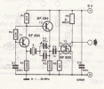
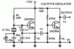
Quartz crystal oscillatorcircuit below should work on the frequency range 1.5 MHz to 8 MHz. A 30 pF of trimmer capacitor is used to adjust the frequency slightly toward the center frequency. 2N3904 transistor functioning as a buffer amplifier to function as a stabilizer frequency and increase the power output. This crystal oscillator circuit can be easily modified to change the frequency of RC components (R1, C1, and C2). Any changes can be monitored by a frequency counter.
1.5 MHz-8 MHz Colpitts Oscillator Circuit with Quartz Crystal
Pierce Quartz Crystal Oscillator
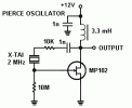
The most simple crystal oscillator circuit is the Pierce oscillator. An FET is used as a amplifying device, as it has a high input resistance, the use of a fence 10M resistance. The crystal has a frequency of 2000 MHz, but a reasonable crystal can be used. 3.3 mH the RF choke provides a high impedance to alternating current load, while the passage of the drain current without the DC voltage drop (the choke had a resistance of 41Ω). The choke must be specially designed to maintain the desired inductance, while wearing DC, so make sure you use the choke is designed for the purpose. The impedance of the coil is then 41k of 2 MHz, which is sufficient amplification.
2 MHz Pierce Oscillator Circuit with Quartz Crystal
Thus, the examples of Quartz Crystal Oscillator Circuit in this usage may shed some light to understand the quartz crystal oscillator.
