Active crossover circuit with TL074
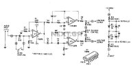
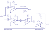
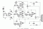
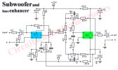
An audio source, like a mixer, preamp, EQ, or a recorder, is fed to the input of the Electronic Crossover Circuit. This signal is either AC or coupling, depending on the setting of switch 51, the non-inverting input of buffer amplifier Ul-a, a section of a quad BIFET, low amp TL074 noise made by Texas Instruments op. This stage has a gain of 2, and its output is distributed to both a low pass filter made by R4, R5, C2, C3, and Uld op-amp, and a high-pass filter made by R6, R7, C4, C5, and op amp ULC. These are12 dB / octave Butterworth filters. The response of the Butterworth filter was chosen because it gives the best compromise between the damping and phase.

The values of capacitors and resistors varies depending on the selected connection that your device works. The filter outputs are fed to a balancing network made by R8, R9, RIO, R14 and potentiometer RLL balance. When the potentiometer is at its center position, there is a unity gain bandwidths for both high and low filters. Power for the electronic circuit is regulated by Crossover R12, RI3, Dl and D2, and decoupled by C6 and C7.
An audio source, like a mixer, preamp, EQ, or a recorder, is fed to the input of the Electronic Crossover Circuit. This signal is either AC or coupling, depending on the setting of switch 51, the non-inverting input of buffer amplifier Ul-a, a section of a quad BIFET, low amp TL074 noise made by Texas Instruments op. This stage has a gain of 2, and its output is distributed to both a low pass filter made by R4, R5, C2, C3, and Uld op-amp, and a high-pass filter made by R6, R7, C4, C5, and op amp ULC. These are12 dB / octave Butterworth filters. The response of the Butterworth filter was chosen because it gives the best compromise between the damping and phase.

The values of capacitors and resistors varies depending on the selected connection that your device works. The filter outputs are fed to a balancing network made by R8, R9, RIO, R14 and potentiometer RLL balance. When the potentiometer is at its center position, there is a unity gain bandwidths for both high and low filters. Power for the electronic circuit is regulated by Crossover R12, RI3, Dl and D2, and decoupled by C6 and C7.
Eklentiler
Son düzenleme:


