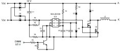
This LED driver electronic circuit is designed using the NCL30100 compact switching regulator controller intended for space constrained constant current high−brightness LED driver applications where efficiency and small size are important. The controller is based on a peak current, quasi fixed−off time control architecture optimized for continuous conduction mode step−down (buck) operation.
NCL30100 controller employs negative current sensing thus minimizing power dissipation in the current sense resistor. The off time is user adjustable through the selection of a small external capacitor, thus allowing the design to be optimized for a given switching frequency range. The control loop is designed to operate up to 700 kHz allowing the designer the flexibility to use a very small inductor for space constrained applications.
The NCL30010 high−brightness LED driver Vcc input can range up to 18 V. For applications that have an input voltage that is greater than that level, an external resistor should be connected between Vin and the VCC supply capacitor.
Design parameters for this LED driver electronic circuit are :
Input voltage: Vin − 12 Vac (12 V dc after the bridge) , Nominal LED current: 700 mA (rms) , LEDripple: 120 mA (peak−to−peak) , VLED: 3.2 V , Freewheel diode Vf: 0.5 V , Target Switching Frequency: 450 kHz , Dimming using PWM signal 1 kHz with duty cycle 0 – 99% .
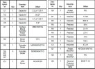
Component required by this constant current high−brightness LED driver project are listed in the table bellow .


