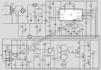
Circuit function generator ICL8038

guclusat

Tanınmış Üye
Süper Moderatör
1643288566364.png
Bill Of Materials For Circuit Function Generator ICL8038
22 Resistors
Quantity:ReferencesValue
1R127k
4R2, R3, R12, R1310k
1R44M7
2R5, R63K3
1R733K
1R822K
1R950k
3R10, R11, R18100k
4R14, R15, R17, R1947k
1R1647R
1R2018k
1R211K8
1R22220R
12 Capacitors
Quantity:ReferencesValue
2C1, C247uF
3C3, C6, C10100nF
1C41nF
1C510nF
1C71uF
1C810uF
1C91000uF
2C11, C1210pF
2 Integrated Circuits
Quantity:ReferencesValue
1U1ICL8038
1U2TL082
10 Miscellaneous
Quantity:ReferencesValue
1J1Out
2RV1, RV2 B10k
2RV2 A, RV3100k
1RV4500R
1RV547k
1SW1SW-ROT-5
2SW2, SW3SW-ROT-3
 

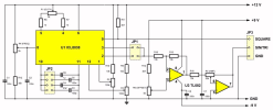
ICL8038 function generator​

- 5 Hz to 50 Hz.
- 50 Hz to 500 Hz.
- 500 Hz to 20 kHz.
- 20 kHz to 400 kHz.
The specifications
The manufacturer promises the following specifications for this kit:
- Frequency range: 5 Hz ~ 400 kHz in four ranges
- Output signals: sine ~ triangle ~ rectangle
- Duty-cycle rectangle wave: 2 % ~ 95 %
- Distortion sine wave: 1 % max after adjustment
- Linearity triangle wave: 0.1 % max
- Temperature drift: 50 ppm/℃
- Offset: -7.5 V ~ +7.5 V
- Amplitude sine and triangle waves: 0.1 Vpeak-to-peak ~ 11.0 Vpeak-to-peak
- Amplitude rectangle wave: 12 V constant
- Power supply: +12 Vdc (+15 Vdc max)
- Current consumption: 20 mA
- Dimensions: 88.2 mm x 61 mm x 18.5 mm
- Weight: 82 g

ICL8038-function-generator-kit-tested-10 (© 2019 Jos Verstraten)

1643289457185.png
1643289466125.png
 

ICL8038 Function Generator​

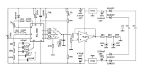
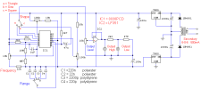
Function generator with adjustable frequency from 0 Hz to over 400 kHz, adjustable amplitude, DC offset, duty, and of course the function selection – square, triangle, and sine. Generator based on good old ICL8038 integrated chip generator that gives pretty good shaped signals as for amateur purposes. This circuit has been designed a little differently than ICL’s note or other similar circuits are suggesting. I tested a bunch of different configurations with different peripherals and chosen the best – so to get good waveshape at 400kHz. I got rid of some of the elements, I added my own solutions. The two ICL chips that i have can oscillate around up to 420-430kHz, and practically we can get good waveforms up to that frequency.
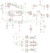
1643289992240.png
The biggest problem of these circuits generators is strong distortion on sine wave output pin 2 at frequencies above 100kHz – so most of the solutions based on this chip has a limited frequency. I found a workaround by not putting the load on the square wave output from pin 9 (open collector that needs to be pulled up to the power supply). In some way the quality of other waveforms is dependent on the load on this pin. Pull-up resistor is activated only when switching output to the square waveform – with the same switch. I got rid of the recommended in the note 10M pot to “improve” the vaweforms. As it turned out its only making them worse, and add a characteristic spout on the top of the upper half of the sine.

Square output pin 9 with open collector, normally would never be able to give a good square wave at these frequencies. Rising edge depends only on the pull-up resistor and its growing very slowly. If we give too strong pull-up resistor, in turn, the trailing edge will be weak because the internal transistor is too heavily loaded. Here, i fixed the square wave with a comparator so that the slope is pretty steep, steep as applied comparator can give. Shown in the schematic LM393 (1.3μs response time) has been replaced by LM293 comparator with 300ns response time – so square wave is acceptable at 400kHz, but it would be good to use even faster model of comparator.

The amplitude of the signal, unfortunately, is not the same for each function, tests have shown that trying to match it with the usual R/R signal dividers will give very distorted waveforms (rounded square and triangle) – so i resigned from such divisors. When ICL is powered from +-12V voltage, it gives VPP voltage waveforms:

Sine = 0.22 * VCC
Triangle = 0.33 * VCC
Square = 0.9 * VCC

We don’t have to concern for the last of them because it gets fed to the input of comparator supplied from +-5V, giving at the output amplitude of signal almost equal to its supply voltage, let’s assume (because each comparator can give different output voltages) that it is a 9.5 VPP (peak to peak). Since the input voltage for the comparator has a greater amplitude than its supply voltage, I decided to fed it just trough the current limiting resistor. Here, the potentiometer is used as a source of compare voltage for the comparator, set it to get the same signal duty that has been set for ICL. Sinusoidal signal coming from the ICL is 5.28 VPP and triangular is 7.92 VPP – so the spread is not that large. A small note here, the scale of the amplitude potentiometer can only have a decorative function or you can match it to only one function. Use of R/R dividers pretty destroys signals, so choice is yours.

Amplitude and DC offset adjustment
Waveforms obtained in this way still need to be fed to the operational amplifier that will allow setting of the amplitude and DC offset. Shown in the schematic TL072 (3MHz and Slew Rate of only 13V/μs) is the absolute minimum that is suitable for such a circuit. Sinusoidal and triangular waveforms will be passed nice, but we can forget about the square. I also tested the NE5532 opamp and it falls considerably worse (10 MHz and slew rate 8V/μs). A LM358 is not even worth of bother. In this case, I used the LM6172 operational amplifier (100MHz and 3000V/μs) which is doing its job great – it passes shape of the rectangle exactly as it got it from the comparator and allows for the full dc offset and amplitude regulations. First half of this opamp is working as repeater, so that the second one that works as an amplifier wont load ICLs signal with its input because they are very “delicate”. +-12V supplied opamp allows for adjusting the amplitude from 0V to 22V. Adding the DC offset regulation to the circuit in such a way that has been done here, has a one disadvantage – waveforms (particularly square) will be having a discharged capacitor effect at a very low frequencies (below 100Hz) – this is the DC offset adjustment potentiometer support capacitor. Its marked as 10uF bipolar on the schematic, but its good to put bigger one to reduce this effect.

The frequency meter has been used in this construction, so its completes the whole generator and allows to perform the frequency adjust without using an external meter or oscilloscope. Shown generator board allows connection of such a meter, giving him power supply and signal to probe. This signal is taken after the waveform switch and is formed in the second half of the above mentioned comparator, and produces a square wave signal with +-5V voltage which its bottom half is then cut off with a 1N4148 diode to the level of -0.7 V. This signal is fed to the meter, the AVR input pin accepts such signals.

Supply
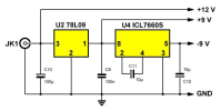
Power supply components included on the board are producing +5 V and-5V for the comparator and frequency meter, and +12 V and-12V for the ICL8038 and operational amplifier. When making this construction and starting it for the first time, make sure that the frequency meter do not draw too much current from the positive line, witch can cause a voltage drop so that 7805 or 7812 stabilizers will experience a drop below their working voltage and give a small sine shaped drops from 50Hz mains – impossible to see without oscilloscope. If this happen, you must increase the capacity of the main filter capacitors or use a more powerful transformer. Voltage transformer should have a 2x14V minimum to allow the proper operation of 7812 and 7912 stabilizers.

Imperfections
In this article i described how to make a simple front panel (its not translated, sorry), and beside regular files such as PCB files, i added a ready-to-print design of the front panel in the PDF format, suitable for housing Z1A, in the attachment. Due to certain limitations of the program in which the panel was designed, scales of the potentiometers provide a full range of regulation, such as duty fill from 0% to 100%, where the circuit does not achieve such regulation. In series with potentiometers, you can try to add resistors so that they will show exactly what generator is doing – i was not playing with this. Duty adjustment is in the range of about 5-10% to 90-95%, is non-linear, and adjusting its lower half reduces the frequency of oscillation for a large values – its a defect or the ICL8038 or it just is designed to work in such way. Offset, amplitude, and frequency scales are pretty accurate.

Shielding, temperature drift
Whole electronic circuit is protected by a tin to minimize the impact of the electromagnetic field of a transformer and power lines. ICL chip changes its oscillation frequency depending on the temperature, so when you turn on the generator, wait approximately two minutes until all the elements get heated to they operating temperature and then fine-tune the frequency. For example, a cold circuit set to 400kHz, decreases its frequency by about 1-2 kHz after warming up. After stabilize, the frequency can change a bit (ICL chip fault), but it should not change over time. For this reason, i do not recommend an active cooling housing – in my case air flow does not exist, and the 7805 can get pretty hot (big current draw by frequency meter) and rise temperature of the whole circuit – I think it even helps to stabilize the temperature.

Additionally
In my version of device i added the input mode for the meter, which can be selected on the range switch, and the output connector can be used to measure external signals. Provide a minimum 0V-3V signal – such signal can be measured by the meter. The signal may be larger, it is matched by the same elements that adjust it at the output of the comparator. Graphics in attachment shows the connections of switches, in this case, I used two rotating ones, 2 x 6 rows each. “Gold-plated” RCA connector is used temporary because I ordered BNCs but they came with a big delay.
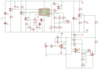
 

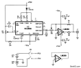
AUDIO GENERATOR CIRCUIT​


1643555819709.png
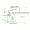
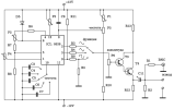
A very compact audio signal generator can be constructed using a precision waveform generator IC (ICL8038) made by Harris Semiconductor. This IC is unique in that it will generate three wave-forms: sine, triangle, and square waves. The frequency output is adjustable between 0.01 Hz and 300 kHz, and the sine-wave output distortion is less than 1 percent. The schematic diagram illustrates the application of the ICL8038 IC to construct a battery-powered mini-audio-signal generator that will provide 500 Hz to 1.5 kHz with adjustable-amplitude output. The output frequency of the generator is set by the combination of R2, R3, and
 

Fonksiyonel üreteci​

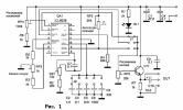
Test fonksiyonel üreteci, hizmet koşullarında doğal sinyal kaynaklarının yerini alan, böylece elektronik cihazın ayrı birimlerini kontrol etmeye ve arıza yerini tek bir birime ve genellikle belirli bir öğeye yerleştirmeye izin veren bir sinyal üretecidir. arızalı cihazı onarmak için. Önerilen devre (Şekil 1) geniş bir frekans aralığında dikdörtgen, üçgen ve sinüzoidal sinyallerin üretecidir. Frekansı (1 Hz 300 kHz) kademeli ve yumuşak bir şekilde ayarlamak ve ayrıca genliği (0- 4 V) üretilen sinyallerin. Cihazın ana unsuru, Amerikan HARRIS SEMICONDUCTOR / Intersil / şirketinin entegre devresi ICL 8038'dir.
1643556259059.png
Frekansın adım değişimi, entegre devrenin 9 girişi ile değerleri alt bantların limitlerini sağlayacak şekilde seçilen C3 C7 güç kapasitörlerinin negatif kutbu arasında bağlı olan anahtarlanarak beş alt bantta gerçekleştirilir. :
I - 1 Hz 70 Hz , II - 70 Hz 700 Hz, III - 700 Hz 7 kHz, IV - 7 kHz 70 kHz, V - 70 kHz 300 kHz. Frekansın düzgün ayarlanması potansiyometre P5 ile ve alt bantların sınırlarının ayarlanması P1 düzeltici ile gerçekleştirilir. Entegre devreden gelen çıkış sinyalleri sırasıyla pinlerden alınır: 2 - sinüzoidal, 3 - üçgen ve 9 - dikdörtgen, genlik eşitlenir ve üç konumlu K2 anahtarının girişlerine beslenir. Çıkış sinyalinin genliği, orta terminali T3 transistörünün tabanına bağlı olan P6 potansiyometresi tarafından ayarlanır. İkincisi, kendisine bağlı Darlington T4 ile birlikte jeneratörün çıkış yükselticisini oluşturur. Sinyalin DC bileşenini çıkarmak için, amplifikatörün çıkış devresine C11 kondansatörü dahildir. P2 düzeltici potansiyometresi, çıkış sinyalini dengeler ve P3 ve P4 düzelticileri, doğrusal olmayan bozulmaların sinyalini temizler. Direnç R1 ile ayrılmış iki çıkış (BNC ve sıradan banana fiş soketleri) vardır.
1643556325409.png
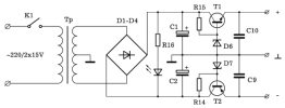
Devre için gerekli olan bipolar güç kaynağı, 220 V / 2x15 V şebeke trafosu ile sağlanır, alternatif voltajı Gretz devresi D1 D4 ile rektifiye edilir ve T1, D6, R15 ve T2 stabilizatörleri ile 12 V seviyelerine stabilize edilir, D7, R14.
Devrenin kendi tüketim akımı 40 mA'dır.
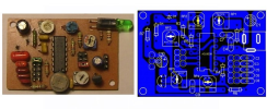
Panonun basılı orijinalini ve elemanların yerlerini aşağıdaki butonlardan indirebilirsiniz. C3 kapasitörlerinin ortak terminali arasındaki bağlantı C7 ve güç kaynağının negatif kutbu, şekilde M - M ile gösterilen bir köprü ile yapılır. Cihazın dış düzenine bir örnek, Şek. 2. Ön panele K1, K2 anahtarları, P5, P6 potansiyometreleri ve çıkış prizleri monte edilecektir. Bunlara bağlantılar, PPMEV 0,2 mm tipi blendajlı kablo ile yapılır. Daha yumuşak frekans kontrolü için P5 potansiyometresi için bir redüktör kullanıldı.
Kullanılan elemanlar :
Dirençler : R1 - 56 OM, R2 - 12 k OM, R3 - 10 k OM, R4 - 56 k OM, R5 - 10 k OM, R6 - 2.4 k OM, R7 - 2.4 k OM,
R8 - 7.72 M OM (4,3 M OM + 3,3 M OM + ) 120 k OM ), R9 - 33 k, OMR10 - 18 k OM, R11 - 20 k OM, R12 - 680 OM,
R13 - 220 OM, R14 - 1.6 k OM, R15 - 1.6 k OM, R16 - 3.3 k OM.

Trimerler ve potansiyometreler : P1 - 1 k OM, P2 - 1 k OM, P3 - 100 kOM, P4 - 100 k OM, P5 - 10 k OM, P6 - 100 k OM.

Kondansatörler : C1 - 2200 mikroF, C2 - 2200 mikroF, C3 - 200 pF, C4 - 2.2 nF, C5 - 22 nF, C6 - 220 nF, C7 - 2.2 mikroF,
C8 - 100 nF, C9 - 0.1 mikroF, C10 - 0.1 mikroF, C11 - 100 mikroF.

Transistörler ve diyotlar : D1 -D5 - 1N4007, D6, D7 - PL12Z, T1 - 2T6551, T2 - 2T6821, T3 - 2T3169C, T4 - 2T6551.
 

Eklentiler

Son düzenleme:
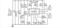
FONKSİYON ÜRETİCİSİ
eknik özellikler:

besleme:
+/-15V​
Tüketim:
30mA​
Maksimum çıkış voltajı:
14Vpp​
Frekans aralığı:
1Hz ila 100KHz​
Dalga formları:
Kare
Üçgen
Sinüzoidal​
Çarpıtma:
< %1​
Aralıklar:
5​
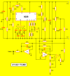
Tüm cihaz, voltaj kontrollü bir osilatör olan entegre ICL8038'de bulunur. Her dalga formu için entegre çıkış seviyesi sabit olduğundan, işlevi önce çıkış voltajını 14Vpp'ye ayarlamak ve sonra bunu dirençli bir ağdan geçirmek olan iki iyi kaliteli işlemsel yükselteçten oluşan başka bir entegre devre dahil edilmiştir. sırasıyla 5V, 0,5V ve 0.05V'lik üç adım sunar (S3 ile seçilebilir). Bu voltajın ince ayarı, sisteme daha fazla hassasiyet kazandırmak için çok turlu olması önerilen P3 potansiyometresi ile yapılır.

Bozulma ayarı, baskılı devre üzerine montaj için ve çok turlu tipte olan ayarlanabilir dirençler RA2 ve RA3 aracılığıyla gerçekleştirilir. P2 potansiyometresi, sinyal simetrisinin ayarlanmasına izin vererek bileşenlerin toleransından kaynaklanan küçük değişiklikleri düzeltmeye izin verir. Testere dişi ve ultra dar darbeler gibi çarpık dalga formları oluşturmak için de kullanılabilir. Çıkış frekansının kontrolü, 1Hz ile 100KHz arasında 10'un katları olarak seçim yapılmasına izin veren S1 seçicisi vasıtasıyla gerçekleştirilir. Potansiyometre P1 söz konusu frekansın ince ayarıdır. Ayrıca çok turlu kullanılması şiddetle tavsiye edilir. 0.01Hz'de salınım imkanı veren 1000µF kapasitöre ulaşmak için daha fazla kondansatör ve daha fazla konuma sahip bir seçici kurulabilir, Bu olağandışı olsa da, uygulayıp uygulamamak sahibine bağlıdır. Potansiyometre P3, ölçek veya aralık seçici olarak S3 ile birlikte çalışan genlik kontrolüdür. Seçici S2, elde edilecek dalga biçimini T üçgen, S sinüzoidal ve C kare olarak seçmenize olanak tanır.

Ekipman kalibrasyonu:

Osiloskop olmadan bile basit ve kolay bir şekilde gerçekleştirmek istiyorsanız bu bir görevdir.

Besleme gerilimi bağlandıktan sonra +/-15V olduğunu kontrol edin. Ardından, dalganın simetrisi ayarlanacaktır. Bir osiloskopunuz varsa, kabloları jeneratörün çıkış fişine bağlamanız gerekir. Dalga formu ölçmek için yeterli genliğe sahip olduğunda, görüntülenen dalga formu simetrik olana kadar P2 kaydırıcısını hafifçe döndürün. Osiloskopunuz yoksa, ayarlanabilir tüm dirençleri orta konumda bırakın. Bozulma ayarı, ayarlanabilir dirençler RA2 ve RA3 aracılığıyla yapılır; bozulma sinüs dalgasında ölçülür. Söz konusu dalga biçiminin elde edilmesi, kesitler halinde doğrusal yaklaşımla gerçekleştirilir, böylece düz çizgiler görünebilir; RA2 ve RA3 merkez konumlarına yakınsa bu çizgilerin beğenilmeme olasılığı vardır. Daha iyi bir tahmin yapmak için, yerel dağıtımın alternatif voltajının sinüs sinyali bir model olarak alınabilir. Bu, osiloskop çift iz olduğu sürece. Ofset voltajı RA1 ile ayarlanır. Sinüs dalgasının rms voltajı bir voltmetre ile kontrol edilebilir. Seçici S3, 5V konumuna yerleştirilmelidir ve sinyal voltajı, dijital voltmetreler için 10KHz'den veya analog voltmetreler için 100Hz'den büyük olmayan bir frekansta ölçülür. Ölçülen voltaj 5V olana kadar RA1'i değiştirin. Bundan sonra, ekipman doğru bir şekilde kalibre edilecek ve çalışmaya hazır olacaktır. Sinüs dalgasının rms voltajı bir voltmetre ile kontrol edilebilir. Seçici S3, 5V konumuna yerleştirilmelidir ve sinyal voltajı, dijital voltmetreler için 10KHz'den veya analog voltmetreler için 100Hz'den büyük olmayan bir frekansta ölçülür. Ölçülen voltaj 5V olana kadar RA1'i değiştirin. Bundan sonra, ekipman doğru bir şekilde kalibre edilecek ve çalışmaya hazır olacaktır. Sinüs dalgasının rms voltajı bir voltmetre ile kontrol edilebilir. Seçici S3, 5V konumuna yerleştirilmelidir ve sinyal voltajı, dijital voltmetreler için 10KHz'den veya analog voltmetreler için 100Hz'den büyük olmayan bir frekansta ölçülür. Ölçülen voltaj 5V olana kadar RA1'i değiştirin. Bundan sonra, ekipman doğru bir şekilde kalibre edilecek ve çalışmaya hazır olacaktır.
1643557474253.png
 
Geri
Yukarı