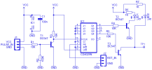
An impulse detector circuit observes input pulses from an external sensor/source and converts into a processable output signal. Described here is a microcontroller-compatible event detector circuit built around one long-familiar CMOS presettable up/down counter chip, CD4029N from Intersil.
Circuit Description
Here, the presettable up/down counter CD4029 (IC1) is configured as upward counting decade counter, resets to zero in a pre-defined routine impelled by an external reset pulse generator. Pulses, for observation, are routed to the clock input of CD4029 through a BC547B (T1) transistor. Green LED (LED1) in the circuit works as “standby” indicator, and the Red LED (LED2) functions as “attention” indicator. Note that, flashes from the Red LED represent a multi-fold increase in events over the Green LED. Events are counted in fixed periods, determined by the external reset pulse generator circuitry. The whole circuit can be connected to any 5V/3.3V dc power supply rails.

Application Example
As stated, this improved impulse detector receives input pulses from an(y) electronic sensor and watch them to produce an alert when necessary. The circuit needs an external time base – the reset pulse generator – for the alert generation task. It is possible to supply the reset pulses from a vacant I/O port of an existing microcontroller (this calls for a few lines of additional code), or from a square wave generator circuit built around discrete components.
Presume that you are building a microcontroller-based spark sensor system using one dedicated spark sensor module as the front-end, and the spark sensor module outputs 8 iterated pulses (per half-second) in case of an unfeigned spark detection. In this circumstance, a 500ms reset pulse should be required for the impulse detector to raise an alert by switching its “attention” LED. Here, flashes from the “attention” LED (red) represent an eight-fold increase in events over the “standby” LED (green). Since the counter reset to zero twice a second, events are counted in 500ms periods. The system diagram shown below may be easier to interpret than the blurring maths.
Circuit Description
Here, the presettable up/down counter CD4029 (IC1) is configured as upward counting decade counter, resets to zero in a pre-defined routine impelled by an external reset pulse generator. Pulses, for observation, are routed to the clock input of CD4029 through a BC547B (T1) transistor. Green LED (LED1) in the circuit works as “standby” indicator, and the Red LED (LED2) functions as “attention” indicator. Note that, flashes from the Red LED represent a multi-fold increase in events over the Green LED. Events are counted in fixed periods, determined by the external reset pulse generator circuitry. The whole circuit can be connected to any 5V/3.3V dc power supply rails.

Application Example
As stated, this improved impulse detector receives input pulses from an(y) electronic sensor and watch them to produce an alert when necessary. The circuit needs an external time base – the reset pulse generator – for the alert generation task. It is possible to supply the reset pulses from a vacant I/O port of an existing microcontroller (this calls for a few lines of additional code), or from a square wave generator circuit built around discrete components.
Presume that you are building a microcontroller-based spark sensor system using one dedicated spark sensor module as the front-end, and the spark sensor module outputs 8 iterated pulses (per half-second) in case of an unfeigned spark detection. In this circumstance, a 500ms reset pulse should be required for the impulse detector to raise an alert by switching its “attention” LED. Here, flashes from the “attention” LED (red) represent an eight-fold increase in events over the “standby” LED (green). Since the counter reset to zero twice a second, events are counted in 500ms periods. The system diagram shown below may be easier to interpret than the blurring maths.
