Adjustable DC Load
To test power supplies, a load of some kind is needed. This can be as simple as a handful of different value power resistors. The gold anodized power resistors made by Dale and others work great. These can be screwed to an aluminum plate or other heat sink to keep their temperatures low. I keep some 1.0, 5.0 and 10.0 ohm, 10W and 25W values around. Put enough of these in series and parallel and you can load down a power supply. But I never have the exact right values and changing the load usually involved soldering. So I built an electronic load. This load applies a constant current to a power supply of between 3V and 30V. My original one used a simple power N-FET bolted to a big heat sink, an op-amp, shunt resistor and voltage reference. It was self powered from 20V down to about 5V and designed for up to 4A loads. Over the years it was upgraded to 10A. Now I use a surplus IGBT which will dissipate 10A at 12V or more (120W) with impunity. I think it's rated to switch 75A at 400V. At 120W, a fan is a must. The circuit is quite simple. Build the electronics on a little Radio-Shack proto-board and mount it on the biggest heat sink in your junk drawer.
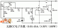
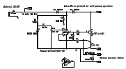
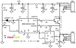
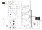
The 1.25V reference diode, 15K resistor, and 10K pot develop a stable 0 to 0.5V. The single-supply op-amp and FET apply the voltage to the 0.05 ohm resistor. 0.5V across 0.05 ohms is 10A maximum. You can parallel multiple larger resistor values if you have trouble finding a 0.05 ohm 10W resistor. To build a 5A load, use a 0.1 ohm, 5W resistor instead. The only trick in building this is to wire the high current path with heavy gauge (16GA or more) wire and treat the 0.05 ohm resistor as a 4-wire device: heavy traces for the high current path, lighter wires soldered to the leads near the body for the voltage measure path. Here is the ExpressPCB schematic. and the .PDF. version. For extra credit, use the unused op-amp and a thermistor to detect when the heat sink gets hot and turn the fan on. The circuit as shown shouldn't be used at more than 18V or so since the full supply can be applied to the FET gate, These are usually rated for 20V max. By removing D3 and always using the external 12V supply, this limitation is removed and the voltage can go up to anything the FET can handle. Watch out for maximum power of the FET though. And remember to de-rate the FET power at high temperatures.


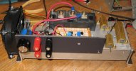
The top binding posts are for the load and the bottom ones for a current monitor via a DMM. The 3 resistors on the right are just spares. Note the big black IGBT in the background, this is in place of the FET in the schematic, but a couple of high power TO-220 or larger N-FETs in parallel will do fine. The big aluminum block is a surplus heat sink with its fins facing down. The brackets on the end keep it somewhat thermally isolated from the bench. With the fan, I have run this beast at 24V and 10A: 240W for short periods of time.
