The following 6 volt 4 AH battery charger circuit has been designed by me and posted here in response to the request from Mr. Raja, let's learn the whole conversation.

The following circuit shows a simple automatic 6 volt 4 AH battery charger circuit without using a relay, rather directly through a transistor.

Update (Jan 05, 2017)
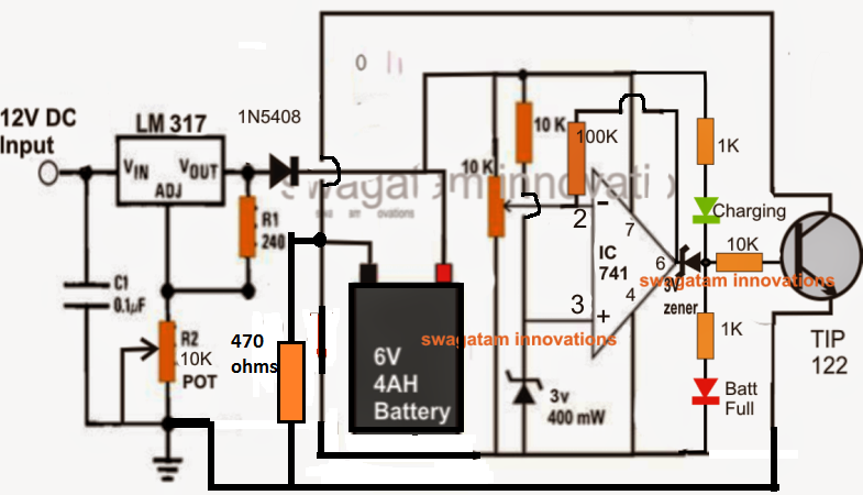
The above transistorized 6V charger circuit has a mistake, and needs to be corrected as illustrated in the following image:

How to Set Up the Circuit
Initially, keep the pin6 feedback resistor disconnected and without connecting any battery adjust R2 to get exactly 7.2V across the output of the LM317, for the IC741 circuit.
Now simply play with the 10k preset and identify a position where the LEDs just flip/flop or change or swap their illumination.
This position within the preset adjustment may be considered as the cut-off or the threshold point.
Carefully adjust it to a point at which the RED LED in the first circuit just lights up......but for the second circuit it should be the green LED that is supposed to get illuminated.
The cut-off point is now set for the circuit, seal the preset in this position and reconnect the pin6 resistor across the shown points.
Your circuit is now set for charging any 6V 4 AH battery or other similar batteries with an automatic cut-off feature as soon as or each time the battery becomes fully charged at the above set 7.2V.
Both the above circuits will perform equally well, however the upper circuit can be altered to handle high currents even up to 100 and 200 AH just by modifying the IC and the relay. The lower circuit may be made to do this only up to a certain limit, may be up to 30 A or so.
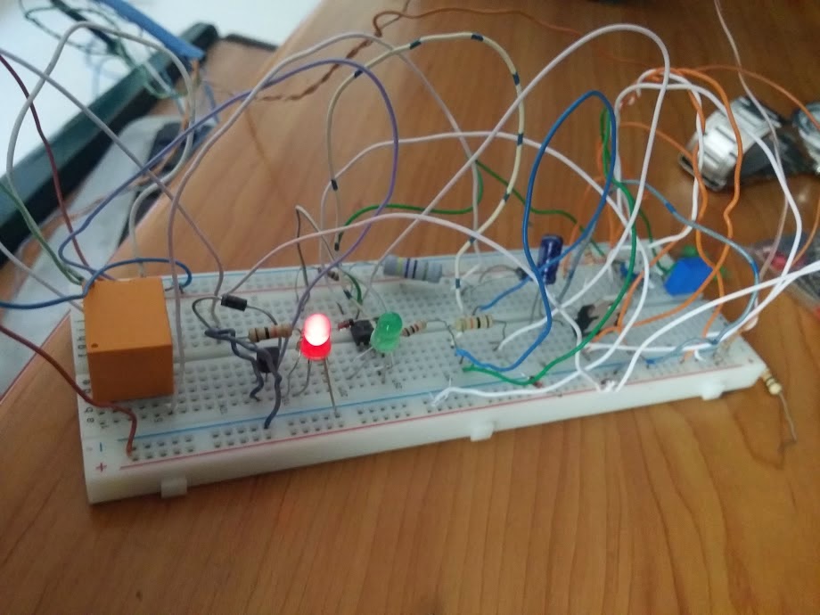
The second circuit from above was successfully built and tested by Dipto who is an avid reader of this blog, the submitted images of the 6V solar charger prototype can be witnessed below:


The following circuit shows a simple automatic 6 volt 4 AH battery charger circuit without using a relay, rather directly through a transistor.

Update (Jan 05, 2017)
The above transistorized 6V charger circuit has a mistake, and needs to be corrected as illustrated in the following image:
How to Set Up the Circuit
Initially, keep the pin6 feedback resistor disconnected and without connecting any battery adjust R2 to get exactly 7.2V across the output of the LM317, for the IC741 circuit.
Now simply play with the 10k preset and identify a position where the LEDs just flip/flop or change or swap their illumination.
This position within the preset adjustment may be considered as the cut-off or the threshold point.
Carefully adjust it to a point at which the RED LED in the first circuit just lights up......but for the second circuit it should be the green LED that is supposed to get illuminated.
The cut-off point is now set for the circuit, seal the preset in this position and reconnect the pin6 resistor across the shown points.
Your circuit is now set for charging any 6V 4 AH battery or other similar batteries with an automatic cut-off feature as soon as or each time the battery becomes fully charged at the above set 7.2V.
Both the above circuits will perform equally well, however the upper circuit can be altered to handle high currents even up to 100 and 200 AH just by modifying the IC and the relay. The lower circuit may be made to do this only up to a certain limit, may be up to 30 A or so.
The second circuit from above was successfully built and tested by Dipto who is an avid reader of this blog, the submitted images of the 6V solar charger prototype can be witnessed below: