Disclaimer: We are not responsible for what you do to your radio, or any damages it may incur during any modifications you perform, or any projects you decide or attempt to build. With that said, perform any modifications or projects at your own risk.
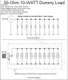
This page shows you the schematic & connection diagram of a basic 50-ohm 10-watt dummy load. This dummy load can be used for CB Radios, ham radios, & various low power transmitters that require a 50-ohm load while testing & tuning.
When tuning or modifying a transmitter you should always do so into a dummy load, not only is it a courtesy to others, but is the proper way to tune a radio as antenna has too many variables, & can be effected by its surroundings that could affect actual load impedance & proper tuning.
Dummy Load basics (resistor type):
A basic dummy load is made up from a NON-INDUCTIVE resistor with a final value of 50-Ohms, so it matches up to 50-Ohm transmitters.
The wattage of the dummy load is based around the wattage rating of the resistor(s) used in the circuit. Generally the higher the wattage rating of the resistor the more power the dummy load can safely handle. The number of resistors used in the circuit depend on there value & your needed power requirements. As an example the dummy load schematic shown here uses ten 500-Ohm resistors with a power rating of 1-watt each. The resistors are all connected in parallel which means as there resistance (ohm) value decreases, there power (watt) rating increases. Use the following basic equations to calculate different value resistors to fit your application.
Basically you can multiply the number of resistors you want to use (for the desired wattage you need) by the impedance of your needed load which is 50-Ohms, to find out what value resistors you need.
Example:
We will be using 1-Watt resistors for this example
We need the dummy load to handle 10-Watts
We need 10, 1-Watt resistors to handle 10 watts
We know we need a final load of 50-Ohms
So basic calculations are:
To find the needed quantity of resistors in the circuit: =
(10 / 1 = 10)
Are target of 10-Watts divided by 1-Watt resistors equals = 10 resistors
To find the needed value for each resistor in the circuit: =
(10 x 50 = 500)
10-Resistors multiplied by 50-Ohms = 500-Ohms
So with a quantity of 10, 500-Ohm resistors in parallel we end up with the needed 50-Ohm final load, & with each resistor having a 1-Watt rating we know our dummy load can dissipate 10-Watts of power as we simply multiply the power rating of one resistor by the quantity used:
(500 / 10 = 50)
500-Ohm divided by 10 resistor = 50-Ohm
(1 x 10 = 10)
1-Watt multiplied by 10 resistors = 10-Watts
So basically, find how many watts you need the dummy load to handle, find what wattage resistors you are going to use, calculate the quantity you need, then calculate the value you need for the resistors in the circuit, then build as shown in the schematic. Although using 1-Watt resistors may not be practical for large dummy loads because as you can see, you need as many resistors as you do watts, so if you were to build a 100-Watt dummy load with 1-Watt resistors you would need 100 resistors in parallel which is not practical. So you would want to select a higher wattage resistor for larger dummy loads. Just make sure the resistors you get are non-inductive (wire wound resistor will NOT work.
For long term reliability, we recommend building a dummy load that can handle at least twice the power then you will be putting into it, so if you need a 10 –Watt dummy load, build a 20-Watt or larger. We have had a 20-Watt dummy load made of 1-Watt resistors in service for many years now & it still functions perfect to this day & it has dissipated over its spec wattage for short term testing more then once with no problems & will easily hold any single or dual final CB or Ham Radios with a PEAK (PEP) power of 40 to 50 watts while tuning.
Schematic & parts connection:
1.) See the schematic for the parts list or calculate the required parts for your dummy load using the above calculations.
2.) Connect the resistors as shown in the schematic & parts connection diagrams.
3.) The resistors should be enclosed in an ALL metal enclosure or metal can to shield stray RF from escaping from the dummy load. The enclosure can contain some vent holes to allow heat to escape (dummy load resistors get hot under use so do not touch them).
4.) Do not allow the positive signal side of the resistors to touch the metal enclosure as it will cause a short & you may blow up your radio, the positive side is the side that connects to the center pin on the SO-239 connector.
5.) This diagram is for basic construction of a dummy load & is only a suggestion, so if you can build a dummy load that can handle more then 10-Watts it is both suggested & recommended.
6.) Most importantly, be careful & have fun!
