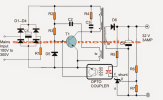
The article presents a 32V, 3 amp SMPS circuit which may be specifically used for driving 100 watt LED modules, rated with the same specs.

How to Wind the Ferrite Transformer
The transformer is wound over a standard EE ferrite core having a central cross sectional area of at least 7 square mm.
Referring to the figure, the upper two primary winding are made up 30 turns of 0.3 mm diameter super enameled copper wire.
The lower primary auxiliary primary winding consists of 4 turns of the same wire as above.
The secondary is wound with 22 turns of 0.6mm super enameled copper wire.
The procedures are as follows:
First begin winding the upper 30 turns, secure its ends on the bobbin leads by soldering, and put a thick layer of insulation tape over these turns.
Next, wind the secondary 22 turns and solder its end terminals on the other side of the bobbin leads, put a layer of thick insulation tape.
Over the above layer start winding the auxiliary 4 turns and as above secure the ends appropriately on the primary side leads of the bobbin, again put some layers of insulation over this,
Finally, wind the second 30 primary turns starting from the previous 30 turn end, and secure the end over one of the leads of the bobbin on the primary side.
Cover the finished winding with additional layers of insulation tapes.
Make sure you remember the terminated leads properly so that you don't make incorrect connections with the circuit and cause a possible fire hazard.
Parts List
All 1 watt, CFR
R1 = 10E
R2 = 1M
R3 = 470E
R4 = 100E
All 1/4 watt MFR 5%
R5 = 470E
R6 = preset 22k
R7 = 2k2
C1 = 10uF/400V
C2 = 2.2nF/250V
C3 = 220pF/1kV
C4 = 2200uF/50V
D1---D4 = 1N4007
D5, D6 = BA159
shunt regulator = TL431
opto = 4n35
T1 = MJE13005

