24V lead acid battery charger circuit

guclusat

Tanınmış Üye
Süper Moderatör
Description.
This lead acid battery charger circuit is designed in response to a request from Mr.Devdas .C. His requirement was a circuit to charge two 12V/7AH lead acid batteries in series.Anyway he did not mentioned the no of cells per each 12V battery. The no of cells/battery is also an important parameter and here I designed the circuit assuming each 12V battery containing 6 cells. When two batteries are connected in series, the voltage will add up and the current capacity remains same. So two 12V/7AH batteries connected in series can be considered as a 24V/7AH battery.

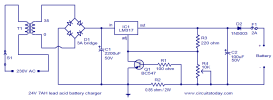
The circuit given here is a current limited lead acid battery charger built around the famous variable voltage regulator IC LM 317. The charging current depends on the value of resistor R2 and here it is set to be 700mA. Resistor R3 and POT R4 determines the charging voltage. Transformer T1 steps down the mains voltage and bridge D1 does the job of rectification. C1 is the filter capacitor. Diode D1 prevents the reverse flow of current from the battery when charger is switched OFF or when mains power is not available.

Circuit diagram.
24V-lead-acid-battery-charger-circuit.png

Notes.

  • Assemble the circuit on a good quality PCB.
  • T1 can be a 230V primary, 35V/3A secondary step down transformer.
  • If 3A Bridge is not available, make one using four 1N5003 diodes.
  • LM317 must be fitted with a heat sink.
  • R2 = 0.85 ohm is not a standard value. You can obtain it by combining a 6.2 ohm and 1 ohm resistors in parallel.
  • F1 can be a 2A fuse.
  • To setup the charging voltage, power ON the charger and hook up a voltmeter across the output terminals and adjust R4 to make the voltmeter read 28V. Now the charger is ready and you can connect the batteries.
  • This charger is specifically designed for two 12V/7AH/6 cell lead acid batteries in series OR a 24V/7AH/12 cell lead acid battery.
 
12V Low Cost Car Battery Charger Circuit PCB

Nowadays it has become necessary to own a car battery charger at home. By keeping one at home, we can avoid car starting trouble due to battery complaints. Buying one battery charger will cost you huge amounts while the components used in the car battery charger schematic is cheap. This charger circuit is designed for 12V car batteries, however we

Battery+charger+circuit.JPG

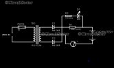
can tweak this circuit for a 24V charger. The charger circuit gives full wave rectified output voltage for charging lead acid batteries. The current reading become almost zero hen the battery is fully charged. the center tapped transformer, the diodes D1 and D2 constitute the unregulated supply portion. The One Ohm wire wound resistor of 10W connected in series controls the charging current and prevents the battery from overcharging. The LED shows the presence of the output voltage. Also its brightness depends on the charging rate.

 
24V to 36V Battery Charger

This 24V to 36V linear battery charger is long overdue. While this is an old circuit technique, it is optimized for charging higher voltage lead-acid battery packs, and could be used on other types of batteries as well. By proper transformer selection, it can be optimized for either 24 or 36V. Note that actual float charge voltage requires 2.4V /cell or 28.8 & 43.2V @ full charge respectively.

Battery Charger Schematic
24-36V-Charger-Schematic.jpg

24-36V-Charger-BOM.jpg

Battery Charger Circuit Description

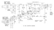
Q1 & Q2 make up a power Darlington using the venerable 2N3055 power transistor. The base of the Darlington is controlled by Q4, the voltage regulator transistor—it compares the feedback voltage coming from the voltage scaling pot with the 6.2V zener reference connected in the emitter circuit. C3 is a compensation capacitor that slows down the regulator in order to prevent potential oscillation.

Instead of using a pull-up resistor to turn the Darlington on, Q3 is configured as a 1mA current source. Working into a current source, Q4 dissipates less power, increases maximum voltage applied to the Darlington and increases voltage regulator gain. High voltage (80V) transistors are required for this application and the MPSA06 and A56 are suggested.

R5 and Q5 make up the current regulator. When the voltage across R5 exceeds about 0.65V, Q5 turns on and shunts base drive from the power Darlington thus causing the output voltage to be reduced. My battery charger circuit ran at 1.1A.

There are two modes of operation—voltage regulation or current regulation—the current regulator (when in operation) takes precedence over the voltage regulator.

Thermal management

I used a puny 5.8°C/W heatsink and while it worked on the bench OK, I recommend a much larger extruded heatsink. I will let you select your own; I did not find an extrusion at DigiKey that was drilled for the TO3 package, so you may have to drill your own heatsink for the 2N3055 transistor. The battery charger circuit has short-circuit protection, but this is momentary at best as the transistor gets very hot. I accidentally shorted the output and yes, the current remained at 1.1A.

Transformer selection

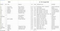
Key to this project is the transformer selection. I started with an old multi-tap Stancor rectifier transformer conservatively rated at 100VA. While this provided the correct DC voltage, I opted to use a smaller 24V transformer that is more representative of what others may have available. Note that the transformer is by far the most expensive item if actually purchased. The BOM indicates an acceptable 24V transformer available at DigiKey. DigiKey does not have an affordable 48V transformer.

To use the 24V transformer, a voltage doubler rectifier is required to obtain the raw 53V supply. Both types of rectifiers are indicated on the battery charger schematic.

Note: to keep the series regulator from having to dissipate an unreasonable amount of power, the raw DC voltage should be about 10V higher than the maximum output voltage. Drop-out voltage is 4.3V—if the raw voltage ever drops below this level, the output drops out of regulation.

Kuberkoos, who suggested this project, will be using a number of transformer secondaries (and/or partial secondaries) connected in series to obtain the required voltage—this also is an acceptable technique.

Getting it up and running

There is much destructive power here so it is wise to bring the voltage up gradually via an adjustable DC power supply or Variac powering the transformer primary. I am glad I did it this way because I had wiring errors that showed up before causing smoke.

What to watch for

When charging a low battery, the regulator will remain in current limit and the voltage will be low until the float charge voltage is reached. At this point, the current will start to decrease.

 
24V battery charger (simple and automatic)


This is a simple 24V battery charger that you can build. The good thing is, you can charge your battery at a high current, 1A up to 20A max if properly constructed (50A is doable when you replace Q4 with higher power capacity). The charger is also automatic, meaning it turns off automatically when battery is fully charged, thus protecting it from damage.

simple+automatic+24v+battery+charger.jpg


charger schematic diagram

Part List:
R1 - 20 kilo ohms 1/4W
R2 - see R2 vs charging current table below for more info
R3 - 2 kilo ohms 1/4W
R4 - 10 kilo ohms 1/4W
R5 - 2 kilo ohms 1/4W
Q1, Q2 - 2N2907, CS9012, 2N4403 or similar PNP transistor
Q3 - 2N2222, CS9013, 2N5551, or similar NPN transistor
Q4 - FQP27P06 or any P-channel Mosfet with higher capacity
Dz - 1N4750A, or any 27V zener diode
DC - 30VDC, 20A max AC-DC converter or DC power supply
Part List diagrams:click image to enlarge

PMOS+pinout.jpg


PMOS pins

pnp+transistor+pin.jpg


2N2907, CS9012 pins

npn+transistor+pin.jpg


2N2222, CS9013 pins

AC-DC+converter+circuit.jpg


AC-DC converter
AC-DC converter Parts:
Transformer - 220V to 22V-0V-22V center tap 600VA
D - D2020L or any rectifier diode rated min 20A
C - 2200uF or 3300uF electrolytic capacitor rated 50V

You can increase or decrease the maximum charging current of your battery by changing the values of resistor R2. The approximate formula for current is given by the equation:
Current = 0.7V / R2 or R2 = 0.7V / Current. See table below for the approximate result.

R2+vs+current+table.jpg


R2 vs charging current table

If you have noticed the table, for you to have a maximum charging current of 1A you need 0.7 ohm R2 rated 1W. Since R2 is not available, you can parallel two resistors to obtain 0.7 ohm value. For example, 1.2 ohm and 1.8 ohm in parallel has an equivalent resistance of 0.72 ohm. For more possible values, you can use the parallel resistor calculator to make calculation easier.

Note: You can increase the value of charging current as high as 50A if you replace the PMOS Q4 with higher power capacity and replace the value of R2. Don’t forget to add a good heat sink.
 

Eklentiler

Geri
Yukarı