12V Otomatik kapanan akü şarj cihazı devresidir..
This 12V auto turn-off battery charger automatically disconnects from mains to stop charging when the battery is fully charged. It serves to charge the battery of our car, using the 120/240 VAC (alternating current), that we have in our house.
If we have this circuit we avoid going to a specialized workshop to perform the charge.
How the 12V Auto turn-off battery charger works?
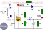
The 12V Auto turn-off battery charger consists of a full-wave rectifier (diodes D1 and D2). The output voltage of the rectifier is pulsating (“m” shaped) and is applied directly to the battery to be charged through the thyristor (SCR1).

When the battery starts charging (it is discharged), the thyristor (SCR2) is in the cut-off state (the thyristor is like an open circuit). This means that the SCR1 thyristor gate has enough voltage to trigger the thyristor and to deliver current to the battery. The current necessary to trigger the SCR comes through the resistor R1.
When the battery charge starts (the battery is discharged) the voltage at the potentiometer slider is low. This voltage is too small to “reverse bias” the 11 volt zener diode. Thus the zener diode is like an open circuit and SCR2 is kept in the cut state.


As the battery charges, the battery voltage increases, as the voltage at the potentiometer slider. Eventually this voltage is enough to “reverse bias” the zener diode and it triggers the SCR2 thyristor which now is like a short circuit.
When the SCR2 thyristor conducts a voltage division is created with R1 and R3 resistors. This voltage division causes the voltage at the anode of diode D3 to be very small and SCR1 thyristor does not conducts, stopping the current flow into the battery. When this occurs the battery is fully charged. If the battery is discharged again, the process starts automatically.
Capacitor C is used, to prevent the thyristor SCR2 from triggering for undesired reasons.
List of 12V Auto turn-off battery charger components
This 12V auto turn-off battery charger automatically disconnects from mains to stop charging when the battery is fully charged. It serves to charge the battery of our car, using the 120/240 VAC (alternating current), that we have in our house.
If we have this circuit we avoid going to a specialized workshop to perform the charge.
How the 12V Auto turn-off battery charger works?
The 12V Auto turn-off battery charger consists of a full-wave rectifier (diodes D1 and D2). The output voltage of the rectifier is pulsating (“m” shaped) and is applied directly to the battery to be charged through the thyristor (SCR1).

When the battery starts charging (it is discharged), the thyristor (SCR2) is in the cut-off state (the thyristor is like an open circuit). This means that the SCR1 thyristor gate has enough voltage to trigger the thyristor and to deliver current to the battery. The current necessary to trigger the SCR comes through the resistor R1.
When the battery charge starts (the battery is discharged) the voltage at the potentiometer slider is low. This voltage is too small to “reverse bias” the 11 volt zener diode. Thus the zener diode is like an open circuit and SCR2 is kept in the cut state.


As the battery charges, the battery voltage increases, as the voltage at the potentiometer slider. Eventually this voltage is enough to “reverse bias” the zener diode and it triggers the SCR2 thyristor which now is like a short circuit.
When the SCR2 thyristor conducts a voltage division is created with R1 and R3 resistors. This voltage division causes the voltage at the anode of diode D3 to be very small and SCR1 thyristor does not conducts, stopping the current flow into the battery. When this occurs the battery is fully charged. If the battery is discharged again, the process starts automatically.
Capacitor C is used, to prevent the thyristor SCR2 from triggering for undesired reasons.
List of 12V Auto turn-off battery charger components
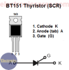
- 1 5 amps or more thyristor (SCR1)
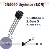
- 1 1 amps thyristor (SCR2)
- 3 47 Ω (ohms) resistors, 2 watts (R1, R2, R3)
- 1 750 Ω (ohms) potentiometer, 2 watts
- 1 1 KΩ resistor (kilohm) (R4)
- 1 50 uF, 25 volts electrolytic capacitor, (uF = microfarads) (C)
- 3 3 amps rectifier diodes (D1, D2, D3)
- 1 11 volt zener diode, 1 watt (Z)
- 1 110/220 VAC to 24 VAC center tapped transformer, 4 amps


