uydudoktoru

Tanınmış Üye
Yönetici
12 Vdc Dual Power Supply circuit with IC 7812&7912

Description
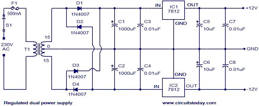
The circuit given here is of a regulated dual power supply that provides +12V and -12V from the AC mains. A power supply like this is a very essential tool on the work bench of an electronic hobbyist.
The transformer T1 steps down the AC mains voltage and diodes D1, D2, D3 and D4 does the job of rectification. Capacitors C1 and C2 does the job of filtering.C3, C4, C7and C8 are decoupling capacitors. IC 7812 and 7912 are used for the purpose of voltage regulation in which the former is a positive 12V regulator and later is a negative 12V regulator. The output of 7812 will be +12V and that of 7912 will be -12V.

Circuit diagram with Parts list

Notes
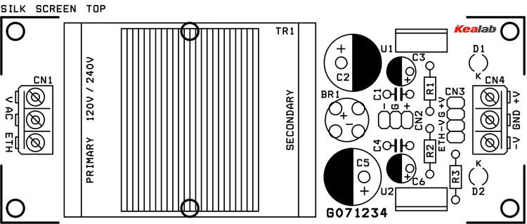
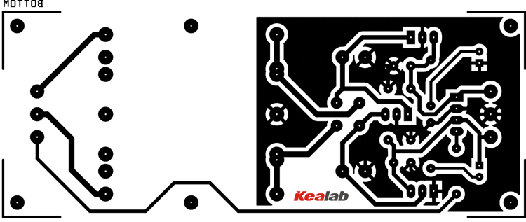
  • Assemble the circuit on a good quality PCB.​
  • Transformer T1 can be a 230V primary; 15-0-15 V, 1A secondary step-down transformer.​
  • Fuse F1 can be a 500mA fuse.​
  • Capacitor C1,C2,C5 and C6 must be rated at least 50V.​
 

Eklentiler

  • regulated-dual-power-supply-circuit.webp
    regulated-dual-power-supply-circuit.webp
    31 KB · Görüntüleme: 7
Son düzenleyen: Moderatör:
+/-12V DUAL POWER SUPPLY

Product_Image.webp
This project is a solution to power up most of devices or projects requiring dual (+/-12V) power supply.

DESCRIPTION

Symmetric +/-12 VDC power supply has been designed for audio applications, can power up microphone pre-amplifier, audio buffers, audio mixer, distributions amplifier, headphone amplifier, VU meter and few o other equipment or projects required dual supply.

SPECIFICATIONS

    • Mains supply input 240 VAC
    • Step Down Transformer 15-0-15V AC @ 350mA.
    • Output +/- 12 VDC Dual, 350 mA
    • Regulated Low ripple DC output
    • Earth connection for chassis ground
    • Onboard regulator for stable supply
    • Dual output LED indication
    • Supply input & output via screw terminal connector
    • Dual unregulated output +/- 22 VDC via berg connector
SCHEMATIC
Schematic42-e1427710911329.webp
PARTS

BOM_th-e1427710969660.webp
PCB


Eklentiler

Son düzenleme:
Elektronik devrelerin ve uygulamaların çoğunlukla 5, 12 ve 15 Volt aralığındaki DC voltajda çalıştığını görüyoruz; bu nedenle üç farklı çift güç kaynağı devresi yapacağız. Tüm devrelerde ayrı ayrı düşürücü transformatörler ve voltaj regülatörleri bulunmaktadır; isterseniz bir LED göstergesi de ekleyebilirsiniz. Devreler şu şekilde listelenmiştir:
  • 9 Volt Çift güç kaynağı devresi
  • 12 Volt Çift güç kaynağı devresi
  • 15 Volt Çift güç kaynağı devresi
1774156214786.webp
12 volt
1774156237768.webp
15volt
1774156251326.webp
 

Eklentiler

Son düzenleme:

1774156395848.webp

Devre Hakkında Kısa Bir Teknik Hatırlatma:​

Bu tip simetrik (dual) devrelerde stabiliteyi artırmak için dikkat edebileceğin birkaç nokta:
  • Isı Yönetimi: 7812 ve 7912 entegreleri doğrusal (linear) regülatörler olduğu için, giriş ve çıkış voltajı arasındaki fark ısıya dönüşür. Özellikle yüksek akım çekilecekse her iki entegreye de uygun boyutlu soğutucu takılmalıdır.
  • Kondansatör Seçimi: Giriş katındaki filtre kondansatörlerinin (genellikle 2200uF veya 4700uF) voltaj değerinin, trafodan gelen AC voltajın tepe değerinden (Vrms x 1.41) en az %20-30 daha yüksek seçilmesi uzun ömürlülük açısından kritiktir.
  • Ters Akım Koruması: Çıkıştan girişe olası bir ters akımı önlemek için entegrelerin giriş ve çıkış bacakları arasına ters bağlı birer koruma diyodu (1N4007 gibi) eklemek devreyi daha güvenli hale getirir.
 
Geri
Yukarı