Güncel olmayan bir tarayıcı kullanıyorsunuz. Bunu veya diğer web sitelerini doğru şekilde görüntülemeyebilir.
Yeni sürüme geçmeli veya bir alternatif kullanmalısınız. tarayıcı.
Yeni sürüme geçmeli veya bir alternatif kullanmalısınız. tarayıcı.
bilgin. 055
Moderator
Circuit Description
Devre Açıklaması
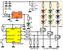
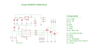
Bu devre aslında bu web sitesindeki başka bir yerde 5 mm LED'leri kullanan daha küçük RGB sürücüsüyle aynıdır, ancak bu sürüm, soğutucu olmadan her kanalda 3 amper tüketebilen yüksek güçlü MOSFET'ler kullanır (5 amperde MOSFET'ler ısınır)
Panele gelen giriş gücü DC olarak düzenlenmeli ve çıkış yükünün güç gereksinimlerini karşılayabilecek kapasitede olmalıdır.
Devre, 9 ila 18 volt aralığında bir besleme voltajıyla çalışacaktır. Bu voltaj aralığı, 78L05 voltaj regülatörünün ve C3/4 kapasitörlerinin giriş gereksinimlerine göre belirlenir.
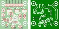
Switch S2, bu web sitesindeki ürün yazılımıyla birlikte kullanılmaz ve onu takmanıza gerek yoktur. Bunu PCB tasarımına dahil ettim çünkü kodun iki anahtar gerektiren bazı özelleştirilmiş versiyonlarını yazdım.
Ne kadar güce dayanabilir?
Test sırasında denetleyiciyi her kanalda bir tane olmak üzere bazı 50W / 12Volt halojen sarkıt ampullere bağladım ve ardından bunları %100 PWM görev döngüsünde çalıştırdım.
Test sırasında ortam sıcaklığı 22oC
5 dakika sonra MOSFET sıcaklığı (metal sekmede ölçülmüştür) 52oC
Akım (kanal başına alıcı) 4,4A
MOSFET Kaynak-Drenaj terminali boyunca voltaj düşüşü (ölçülen) 20mV
Bu ölçümlere ve MOSFET'lerin ve PCB konnektörlerinin spesifikasyonlarına bağlı olarak kontrol cihazının kanal başına 3 amperi rahatlıkla idare etmesi gerekir. Bireysel MOSFET'ler daha fazla akımı kaldırabilse de, PCB vidalı terminal konnektörleri 16 amper olarak derecelendirilmiştir ve karta yalnızca tek bir Toprak bağlantısı olduğundan, üç RGB kanalının toplam yükü bunu aşmamalıdır.
ÇevirisiThis circuit is essentially the same as the smaller RGB driver using the 5mm LEDs elsewhere on this website except that this version uses high power MOSFETs capable of sinking 3 amps on each channel without heatsinks (at 5amps the MOSFETs will run hot)
The input power to the board must be regulated DC and be capable of suppling the power requirements of the output load.
The circuit will operate from a supply voltage in the range 9 to 18 volts. This voltage range is dictated by the input requirements of the 78L05 voltage regulator and capacitors C3/4.
Switch S2 is not used with the firmware on this website and you do not need to fit it. I've incorporated it the PCB design because I've written some customized versions of the code that did require two switches.
How much power can it handle?
During testing I connected the controller to some 50W / 12Volt halogen downlight bulbs, one on each channel then ran them at 100% PWM duty cycle.
Based on these measurements and the specification of the MOSFETs and PCB connectors, the controller should comfortably handle 3 amps per channel. While the individual MOSFETs could handle more current, the PCB screw terminal connectors are rated at 16 amps and since there is only a single Ground connection to the board, total load for the three RGB channels should not exceed this.
Ambient temperature during test 22oC MOSFET temperature after 5mins (measured on metal tab) 52oC Current (sink per channel) 4.4A Voltage drop across MOSFET Source-Drain terminal (measured) 20mV
Devre Açıklaması
Bu devre aslında bu web sitesindeki başka bir yerde 5 mm LED'leri kullanan daha küçük RGB sürücüsüyle aynıdır, ancak bu sürüm, soğutucu olmadan her kanalda 3 amper tüketebilen yüksek güçlü MOSFET'ler kullanır (5 amperde MOSFET'ler ısınır)
Panele gelen giriş gücü DC olarak düzenlenmeli ve çıkış yükünün güç gereksinimlerini karşılayabilecek kapasitede olmalıdır.
Devre, 9 ila 18 volt aralığında bir besleme voltajıyla çalışacaktır. Bu voltaj aralığı, 78L05 voltaj regülatörünün ve C3/4 kapasitörlerinin giriş gereksinimlerine göre belirlenir.
Switch S2, bu web sitesindeki ürün yazılımıyla birlikte kullanılmaz ve onu takmanıza gerek yoktur. Bunu PCB tasarımına dahil ettim çünkü kodun iki anahtar gerektiren bazı özelleştirilmiş versiyonlarını yazdım.
Ne kadar güce dayanabilir?
Test sırasında denetleyiciyi her kanalda bir tane olmak üzere bazı 50W / 12Volt halojen sarkıt ampullere bağladım ve ardından bunları %100 PWM görev döngüsünde çalıştırdım.
Test sırasında ortam sıcaklığı 22oC
5 dakika sonra MOSFET sıcaklığı (metal sekmede ölçülmüştür) 52oC
Akım (kanal başına alıcı) 4,4A
MOSFET Kaynak-Drenaj terminali boyunca voltaj düşüşü (ölçülen) 20mV
Bu ölçümlere ve MOSFET'lerin ve PCB konnektörlerinin spesifikasyonlarına bağlı olarak kontrol cihazının kanal başına 3 amperi rahatlıkla idare etmesi gerekir. Bireysel MOSFET'ler daha fazla akımı kaldırabilse de, PCB vidalı terminal konnektörleri 16 amper olarak derecelendirilmiştir ve karta yalnızca tek bir Toprak bağlantısı olduğundan, üç RGB kanalının toplam yükü bunu aşmamalıdır.
| Description | Filename | Download link |
| Version 2 Source code | rgbsa-inet.zip V2.0.2 09/06/2007 |  download download |
| V2 HEX file ready to program for 12F629/675 | rgbsa-int675.HEX V2.0.2 09/06/2007 |  download download |
| V2 HEX file ready to program for 12F683 | rgbsa-int683.HEX V2.0.2 09/06/2007 |  download download |
| Version 3 Source code | genRGBsa.zip V3.0.3 28/09/2008 |  download download |
| V3 HEX file ready to program for 12F629/675 | rgbsa303_629.HEX V3.0.3 28/09/2008 |  download downloadchecksum 97E0 |


