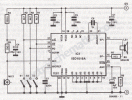
This voice or sound recorder built with ISD1012, ISD1016 and ISD1020 which are produced by ISD and allow sound voice recording and play-back. The last 2 digits show the maximum legth of recording time in seconds. This circuits contains a non-volatile memory which can memorise sound or voice without power supply up to 10 years. The circuit contains a microphone amplifier and a speaker amplifier. We can say its a digital voice recorder.
S1 switch is for recording / play-back ( recording in ON position ). When S2 is OFF the IC goes in power down mode. S3 starts the recording or play-back and must be a push-button.
For more voice recorder circuits check the list bellow.
Sound recorder circuit diagram

S1 switch is for recording / play-back ( recording in ON position ). When S2 is OFF the IC goes in power down mode. S3 starts the recording or play-back and must be a push-button.
For more voice recorder circuits check the list bellow.
Sound recorder circuit diagram

Son düzenleme:
