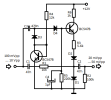
This mini audio compressor circuit use only one active component T1. The audio signal goes thru C1, R1, D1, C2, R3. Still a part of audio signal charge the D3/D4 detector and creates a control voltage for T1.
The fading time depends on C4 and R5. With an audio input variation of 50dB, the output signal get is +-3dB. You can use this audio compressor circuit in a transmitter.
Schematic of Audio Compressor Circuit

The fading time depends on C4 and R5. With an audio input variation of 50dB, the output signal get is +-3dB. You can use this audio compressor circuit in a transmitter.
Schematic of Audio Compressor Circuit

Eklentiler
Son düzenleme:
