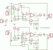
With this circuit we recompense the human ear deficiency to perceive less sharp and less deep tones of those that a melody really has at low volume.
In the following graphic we can see how a human ear perceives different frequencies depending on the sound pressure (the volume).
They are called equal loudness contours. Two tones that have different frequencies and the same sound intensity are perceived differently.
With this circuit we compensate that low and high frequencies loss that we experience when we listen to the music with low volume.
The circuit is quite simple and it is based on an operational type TL072, or equivalent, and on a filter which is in charge of executing low and high frequencies of 12DB order. We can experiment as much as we like, while trying to change filter values, from R7, C6, C5, C4, R4 in the right channel and R10, C15, C14, C13, R16 in the left channel.
The filter is placed just before the amplifier’s volume control.
The power can range from 10 to 22 volts in the direct current, and we can take it from the amplifier’s power source.
Of course, it has to be stabilized and filtered to avoid noise at the output. The input and output circuit connection cables are to be shielded.

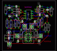
The scheme and the circuit board should be in the same folder and they should have the same name, you should only change the extension to .sch for the scheme and to .brd for the circuit board, this way both of them will be recognized and associated by Eagle.
