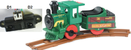
This simple and economical IR model train detector circuit is intended especially for those hobbyists who wish to add a smart sensor to detect trains on their model railway track. As can be seen in the schematic diagram, it comprises of a simple infrared transmitter and receiver wired around the good old PLL Tone Decoder LM567(IC1). It has a working range of around 10 to 50 cm. Output of the detector is galvanically isolated with the help of a standard opto-coupler CNY18-2 (IC2), which can be suitably interfaced to any external circuit for further processing task(s).
Schematic of the Model Train Detector Circuit

Working of the circuit is straight forward. When light from Infrared sender (D1) is relected by the wagon of the model train, IC1 through Infrared photo sensor (D2) receives the recovered signal at its input point (pin3). If PLL (IC1) is locked, its output (at pin8) drops low, thus disabling the optocoupler IC2 for the specific time and this process repeats based on the number of wagons.Infrared componets D1 and D2 should be mounted such that D2 can only pick up reflected light. When a train passes, the infrared light is reflected at certain intervals, which produces a sort of pulse code for the train. Using an external circuit connected through IC2, it is possible to distinguish various model trains from each other using the pulse code! The choice of D1 and D2 is not very critical, but they must be band compatible. Operating point of the detector is dependent on refleted light levels and value of the resistor R2 (here 22K) may need to be tuned for optimum performance.
IR sensor mounting plan

Schematic of the Model Train Detector Circuit

Working of the circuit is straight forward. When light from Infrared sender (D1) is relected by the wagon of the model train, IC1 through Infrared photo sensor (D2) receives the recovered signal at its input point (pin3). If PLL (IC1) is locked, its output (at pin8) drops low, thus disabling the optocoupler IC2 for the specific time and this process repeats based on the number of wagons.Infrared componets D1 and D2 should be mounted such that D2 can only pick up reflected light. When a train passes, the infrared light is reflected at certain intervals, which produces a sort of pulse code for the train. Using an external circuit connected through IC2, it is possible to distinguish various model trains from each other using the pulse code! The choice of D1 and D2 is not very critical, but they must be band compatible. Operating point of the detector is dependent on refleted light levels and value of the resistor R2 (here 22K) may need to be tuned for optimum performance.
IR sensor mounting plan

Son düzenleme:
