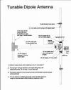
A simple dipole antenna can be used for improved reception of FM broadcast signals. A dipole is basically a length of conductor (wire) split into two portions and signal is taken off at the split. It has a nominal 3 dB gain over an isotropic source and is directional, tending to favor signals coming broadside to the wire. The dipole is customarily an electrical half wavelength of wire at the frequency of interest, since the impedance under this condition is theoretically 72 ohms resistive and is a good match to a 50-75 ohm source or load generally presented by interfacing equipment such as receivers and transmitters designed to work into this range of impedances.
The length of a half wave dipole in feet is calculated as 468 divided by the frequency in MHz or in inches as 5606/F mhz. This takes "end effect" into consideration, and also the fact that the dipole elements are of finite thickness, and works out as pretty close in practice. Therefore, a dipole for 98 MHz which is band center of the FM broadcast band, works out to 4.78 feet or 57.3 inches. The dipole would then consist of two lengths of wire each 2.39 feet or 28.65 inches long, arranged as shown in the figure.
Coaxial cable can be used to connect to the antenna as shown, but for best results, a balun should be used to prevent feedline radiation or pickup, which tends to distort the pattern. For 88-108 MHz this can be made by winding the coaxial feedline through a toroidal core or around a ferrite rod. The idea is to insert a series impedance to shield currents on the outside of the outer conductor, effectively decoupling it from the antenna. The current inside the line does not see this, as the inner and outer conductors are carrying equal and opposite currents and produce no external magnetic field, so no loss is experienced. The ferrite can be almost anything that yields a high impedance at the operating frequency. For 88 MHz to 108 MHz, this can be a small toroid or rod with 3 to 4 turns of the cable. See Figure. We used a ferroxcube 768T188-4C4 material specified for 1 to 20 MHz, wound with 3 turns of RG 174/U miniature coax. The measured loss was 0.3 dB including two connectors in the test setup, and the impedance across the toroid effectively in series with the outer surface of the shield was 1100 ohms shunted by -1.2 pf as read on a Boonton RX meter. This is over 10 times the feedline impedance and should be adequate.
The antenna should be mounted high and in the clear for very best results (30 feet away from anything else) and oriented facing favored direction of reception.
Fm 88mhz ile 108mhz arası dpol anten


Son düzenleme:
