Circuit of potent transmitter of FM with transistor 2n2218
This small transmitter can arrive the more than 1 km in favorable conditions of emission. The modulation can be made so much with a microphone, for an electrets microphone, or other audio source.
 The 5 turns of enameled thread 22 AWG, with diameter of 1 cm without nucleus. Look at the capacitors that it should be ceramic. The antenna should possess from 15 to 40 cm. Para the transmission it ties a receiver of FM (radio) in the proximities to half volume in a free frequency (that there is not any radio operating), with a wood or plastic key, rotate the screw of CV to capture the sign more fort of the transmitter, because a spurious sign can be captured. If it has difficulties of fittings, remove the coil and wind her again with more or less it turns. Look at pinage of the transistor 2n2218. Mic1 is a microphone of electrets of two terminals, THE resistor R1 makes the polarization of the microphone, perhaps it is necessary to alter the value of R1 to adapt to your microphone, values of 1k up to 10k can be tested. Preferably use plate of glass fiber, that is the appropriate for high frequency. Perhaps for better frequency stability to be necessary to place the antenna on second turn of the coil, weld the thread piece used as antenna second it turn of the coil L1.
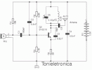
Below we have the schematic of the one of the circuit of the transmitter of FM
It can be necessary special authorization to operate this equipment in that potency.
 List of Material for assembly of the fm transmitter
Resistors 5% 1/4 w:
R1 = 3 a 10kΩ (black, black, orange, gold)
R2 = 6,8kΩ (Blue, Gray, red, gold).
R3=4,7kΩ (yellow, violet, red, gold. )
R4 = 39Ω (Orange, White, black, gold.
Ceramic Capacitors
C1=4,7 nF (472 or 4n7 or 4700)
C2=2,2 nF (2200 or 2n2 or 222)
C3 = 4.7pF (4p7 or 4.7)
C4 = 100 nF (100n, or 0.1 or 104)
C5 = TRIMMER CV 3-30 PF.
Transistor:
T1 = 2n2218 or equivalent.
Several:
L1 = see the text
B1 = Battery of 9 volts alkaline.
Mic1 = electret microphone.
Several = printed circuit board, antenna, box, etc.
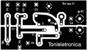
Board fm transmitter side of the copper Scale 3:1

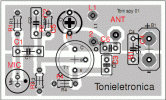
Board fm transmitter side of the components

Pinage of the transistor 2N2218 sees underneath

This small transmitter can arrive the more than 1 km in favorable conditions of emission. The modulation can be made so much with a microphone, for an electrets microphone, or other audio source.

Below we have the schematic of the one of the circuit of the transmitter of FM
It can be necessary special authorization to operate this equipment in that potency.

Resistors 5% 1/4 w:
R1 = 3 a 10kΩ (black, black, orange, gold)
R2 = 6,8kΩ (Blue, Gray, red, gold).
R3=4,7kΩ (yellow, violet, red, gold. )
R4 = 39Ω (Orange, White, black, gold.
Ceramic Capacitors
C1=4,7 nF (472 or 4n7 or 4700)
C2=2,2 nF (2200 or 2n2 or 222)
C3 = 4.7pF (4p7 or 4.7)
C4 = 100 nF (100n, or 0.1 or 104)
C5 = TRIMMER CV 3-30 PF.
Transistor:
T1 = 2n2218 or equivalent.
Several:
L1 = see the text
B1 = Battery of 9 volts alkaline.
Mic1 = electret microphone.
Several = printed circuit board, antenna, box, etc.
Board fm transmitter side of the copper Scale 3:1

Board fm transmitter side of the components

Pinage of the transistor 2N2218 sees underneath

Eklentiler
Son düzenleme:


