Arduino is an open-source electronics prototyping platform based on flexible, easy-to-use hardware and software. Anyone interested in creating interactive objects can “play” with Arduino! Described here is an interesting circuit of an Arduino-based Christmas LED Light Bar. It is very simple so that even a novice can build it without any difficulty.
It is infact a 3-channel sequential LED driver with a “speed control” potmeter to change the display effect.
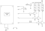
Schematic of the Arduino Xmas Lights Circuit

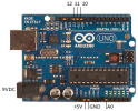
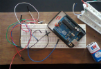
Arduino is here introduced intentionally because of its tractability which allows interested hobbyists to start their own experiments with this project for adding more light channels and/or visual effects by tweaking the hardware (Arduino + auxiliary electronics) and the software (Arduino sketch/code).
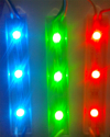
The major component, in addition to Arduino board is the LED light bar. The LED Bar is a prepackaged strip of 3 high-output LEDs powered by 12VDC. Each unit comes with a fully assembled and tested PCB with current limiting resistors, a wall-mount holder and peel-away sticky foam backing, and polarized connection wires. Each Bar absorbs approximately 60-65mA at 12V. Here three such LED light bars (one Red, one Green and one blue) are used to complete the circuit. Use a standard 9V battery to power the arduino board, and use a suitable 12VDC adaptor for powering the light bar section as shown in the schematic diagram.
Arduino Sketch


It is infact a 3-channel sequential LED driver with a “speed control” potmeter to change the display effect.
Schematic of the Arduino Xmas Lights Circuit

Arduino is here introduced intentionally because of its tractability which allows interested hobbyists to start their own experiments with this project for adding more light channels and/or visual effects by tweaking the hardware (Arduino + auxiliary electronics) and the software (Arduino sketch/code).
The major component, in addition to Arduino board is the LED light bar. The LED Bar is a prepackaged strip of 3 high-output LEDs powered by 12VDC. Each unit comes with a fully assembled and tested PCB with current limiting resistors, a wall-mount holder and peel-away sticky foam backing, and polarized connection wires. Each Bar absorbs approximately 60-65mA at 12V. Here three such LED light bars (one Red, one Green and one blue) are used to complete the circuit. Use a standard 9V battery to power the arduino board, and use a suitable 12VDC adaptor for powering the light bar section as shown in the schematic diagram.
Arduino Sketch
Kod:
int delayTime = 0;
void setup()
{
   pinMode(12, OUTPUT);
   pinMode(11, OUTPUT);
   pinMode(10, OUTPUT);
}
void loop()
{
   delayTime = analogRead(0);
   digitalWrite(12, HIGH);
   delay(delayTime);
   digitalWrite(12, LOW);
   delay(delayTime);
   digitalWrite(11, HIGH);
   delay(delayTime);
   digitalWrite(11, LOW);
   delay(delayTime);
   digitalWrite(10, HIGH);
   delay(delayTime);
   digitalWrite(10, LOW);
   delay(delayTime);
}


