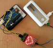
8×8 LED Matrix modules are now widely available, and fortunately they are easy to use with our favorite Arduino microcontroller. 8×8 LED Matrix module have many applications in real life, such as various types of electronic display panels.
The LED matrix can be driven in two ways (parallel or serial). Here we drive it in the serial manner in order to save interface (needs only three data lines). The serial-driven LED matrix actually dynamically displays the LEDs (row-by-row or column-by-column). The persistence of vision for humans is about 0.1s, so as long as we can serially display all 8 rows/columns within 0.1s, we’ll see a complete character or pattern.

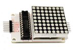
Our project is infact an Arduino with Serially Interfaced MAX7219 Operates an 8X8 LED Matrix to display a heart pattern. The MAX7219 IC is a serial input/output common-cathode display driver that interfaces microprocessors to a 7-segment numeric LED displays of up to 8 digits, bar-graph displays, or 64 individual LEDs. For convenience, here an 8×8 LED matrix, integrated with a MAX7219 IC setup, available as a pre-wired module is used. Typical specification of this LED Matrix Module is shown below:

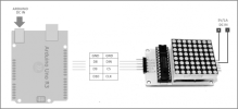
Wiring Instructions
Wiring Diagram

Warning!
Before powering up, ensure that corresponding wires are properly connected.
Arduino Sketch
The LED matrix can be driven in two ways (parallel or serial). Here we drive it in the serial manner in order to save interface (needs only three data lines). The serial-driven LED matrix actually dynamically displays the LEDs (row-by-row or column-by-column). The persistence of vision for humans is about 0.1s, so as long as we can serially display all 8 rows/columns within 0.1s, we’ll see a complete character or pattern.

Our project is infact an Arduino with Serially Interfaced MAX7219 Operates an 8X8 LED Matrix to display a heart pattern. The MAX7219 IC is a serial input/output common-cathode display driver that interfaces microprocessors to a 7-segment numeric LED displays of up to 8 digits, bar-graph displays, or 64 individual LEDs. For convenience, here an 8×8 LED matrix, integrated with a MAX7219 IC setup, available as a pre-wired module is used. Typical specification of this LED Matrix Module is shown below:
- Operating Voltage: DC 4.7V – 5.3V
- Typical Voltage: 5V
- Operating Current: 320mA
- Max Operating Current: 2A

Wiring Instructions
- Connect Arduino pin8 to DIN on 8×8 LED Matrix
- Connect Arduino pin9 to CS of 8×8 LED Matrix
- Connect Arduino pin10 to CLK of 8×8 LED Matrix
- Connect an external 5VDC (1A) to VCC of 8×8 LED Matrix
- Connect external 5VDC supply’s GND, to the GND of 8×8 LED Matrix Module
Wiring Diagram

Warning!
Before powering up, ensure that corresponding wires are properly connected.
Arduino Sketch
Kod:
/*
* Arduino Sweet Heart
*  An Arduino & 8x8 LED dot matrix project
* Using Max7219 IC
* Designed by T.K.Hareendran
* Tested at TechNode Protolabz
* 17 July 2014
* http://www.electroschematics.com
*/
unsigned char i;
unsigned char j;
int Max7219_pinCLK = 10;
int Max7219_pinCS = 9;
int Max7219_pinDIN = 8;
unsigned char disp1[19][8]={
  0x00, 0x00, 0x00, 0x00, 0x00, 0x00, 0x00, 0x00, // Heart Pattern
  0x00, 0x00, 0x00, 0x00, 0x40, 0x00, 0x00, 0x00,
  0x00, 0x00, 0x00, 0x40, 0x40, 0x00, 0x00, 0x00,
  0x00, 0x00, 0x80, 0x40, 0x40, 0x00, 0x00, 0x00,
  0x00, 0x80, 0x80, 0x40, 0x40, 0x00, 0x00, 0x00,
  0x40, 0x80, 0x80, 0x40, 0x40, 0x00, 0x00, 0x00,
  0x60, 0x80, 0x80, 0x40, 0x40, 0x00, 0x00, 0x00,
  0x60, 0x90, 0x80, 0x40, 0x40, 0x00, 0x00, 0x00,
  0x60, 0x90, 0x88, 0x40, 0x40, 0x00, 0x00, 0x00,
  0x60, 0x90, 0x88, 0x44, 0x40, 0x00, 0x00, 0x00,
  0x60, 0x90, 0x88, 0x44, 0x44, 0x00, 0x00, 0x00,
  0x60, 0x90, 0x88, 0x44, 0x44, 0x08, 0x00, 0x00,
  0x60, 0x90, 0x88, 0x44, 0x44, 0x08, 0x10, 0x00,
  0x60, 0x90, 0x88, 0x44, 0x44, 0x08, 0x10, 0x20,
  0x60, 0x90, 0x88, 0x44, 0x44, 0x08, 0x10, 0x60,
  0x60, 0x90, 0x88, 0x44, 0x44, 0x08, 0x90, 0x60,
  0x60, 0x90, 0x88, 0x44, 0x44, 0x88, 0x90, 0x60, // Heart Pattern
};
void Write_Max7219_byte(unsigned char DATA)
{
  unsigned char i;
  digitalWrite(Max7219_pinCS,LOW);
  for(i=8;i>=1;i--)
  {
    digitalWrite(Max7219_pinCLK,LOW);
    digitalWrite(Max7219_pinDIN,DATA&0x80);
    DATA = DATA<<1;
    digitalWrite(Max7219_pinCLK,HIGH);
  }
}
void Write_Max7219(unsigned char address,unsigned char dat)
{
  digitalWrite(Max7219_pinCS,LOW);
  Write_Max7219_byte(address);
  Write_Max7219_byte(dat);
  digitalWrite(Max7219_pinCS,HIGH);
}
void Init_MAX7219(void)
{
  Write_Max7219(0x09, 0x00);
  Write_Max7219(0x0a, 0x03);
  Write_Max7219(0x0b, 0x07);
  Write_Max7219(0x0c, 0x01);
  Write_Max7219(0x0f, 0x00);
}
void setup()
{
  pinMode(Max7219_pinCLK,OUTPUT);
  pinMode(Max7219_pinCS,OUTPUT);
  pinMode(Max7219_pinDIN,OUTPUT);
  delay(50);
  Init_MAX7219();
}
void loop()
{
  for(j=0;j<19;j++)
  {
    for(i=1;i<9;i++)
      Write_Max7219(i,disp1[j][i-1]);
    delay(500);
  }
}