This 12V solar charge regulator meets most small-scale application requirements. With a current rating of 6A, it can handle up to a 100W solar panel. Its principle of operation is very simple and there is only one adjustment: cut-out voltage. Many inexpensive commercial solar charges available use, I believe, this technique.
However, this particular design is superior in that it is powered via the solar panel rather than the battery the implications of this are obvious: low battery discharge current. The switching is accomplished via an inexpensive 10A relay. One of the interesting features is the secondary load output that can be used for other purposes within specific loading limits in other words, there are two outputs: one for charging the battery and the other for use when the battery is not charging so that the solar power may be more fully utilized.
The application for this type of charge control is one in which the battery capacity is large in respect to the charging current; e.g. 6A solar panel charging a 60AH battery in which it takes perhaps a full days sunshine to fully charge the battery.
For much smaller batteries, the high charging rate and relatively high battery internal resistance results in excessive terminal voltage so that the control immediately interrupts charging the end result is that the battery cannot charge fully a linear charge regulator is more appropriate in such cases.
All the chargers that I have posted on electroschematics to date (6 in all) have been of the linear type except for the DIY Solar Boost Converter with MPPT Charge Controller. I have plans for a few more solar chargers, so keep watching.
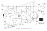
Schematic of the Relay Based Solar Charge Control Circuit

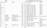
Bill of materials


Circuit function

U2 provides a 5V reference voltage and power for the 555 clock generator. U1 is a LM339 quad comparator connected as a S-R flip flop with wired OR outputs so that it may be conveniently driven via open collector output structure. U3 is a CMOS 555 clock generator that generates 30mS pulses every 30S. Its function is to set the flip flop so that charging may commence. (Another descriptive name for this topology is minimum on-time regulator). D1 effectively changes the totem pole output of the 555 to open collector and D2 limits the voltage excursion to 5V to prevent a 555 malfunction. As soon as the battery terminal voltage exceeds the set point (14.5V or so), comparator U1D resets the flip flop and drops the relay.
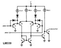
At this point, it remains dormant until the next clock pulse. When fully charged, the relay flips on and off briefly. U1C and Q1 constitute a relay driver the NPN open collector output of the LM339 and Q1 (PNP) make up the classic composite transistor connection. This is necessary to boost the low power output of the LM339 sufficiently for driving the relay coil check out the LM339 internal circuit:
Secondary output limitation
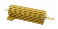
While this neat feature is provided, its application is limited. Note that the load resistance is not allowed to drag the solar panel output below about 11V under marginal lighting conditions or else the relay may not have sufficient voltage to pick up. This load could conceivably operate a low-power heater etc how about a coffee mug heater? The big challenge is to obtain the proper load resistance a number of aluminum resistors such as the Vishay /Dale TMC50 series (see photo) may be a good solution. Also, before selecting the resistors make actual measurements to see what works even then, experimentation may be required for best results.

The current rating is limited by D5 (6A) and the relay contacts (10A). By using a high current rectifier and relay, the current rating may be increased substantially.
Setup
To set the Max Voltage Adjust (R12) potentiometer, start with it turned CW, monitor the voltage and wait for the battery terminal voltage to reach the desired voltage (e.g. 14.5V). At this point, turn R12 CCW until the relay drops. When the relay picks up again, recheck the voltage at which it drops.
Charging a dead battery
If the battery voltage is too low (e.g. 5 or 6V), the relay may drop out immediately due to undervoltage. To get around this problem, connect the solar panel directly to the battery until the voltage charges to at least 10V or so, or flash it by connecting it directly across a charged battery for a few seconds.
However, this particular design is superior in that it is powered via the solar panel rather than the battery the implications of this are obvious: low battery discharge current. The switching is accomplished via an inexpensive 10A relay. One of the interesting features is the secondary load output that can be used for other purposes within specific loading limits in other words, there are two outputs: one for charging the battery and the other for use when the battery is not charging so that the solar power may be more fully utilized.
The application for this type of charge control is one in which the battery capacity is large in respect to the charging current; e.g. 6A solar panel charging a 60AH battery in which it takes perhaps a full days sunshine to fully charge the battery.
For much smaller batteries, the high charging rate and relatively high battery internal resistance results in excessive terminal voltage so that the control immediately interrupts charging the end result is that the battery cannot charge fully a linear charge regulator is more appropriate in such cases.
All the chargers that I have posted on electroschematics to date (6 in all) have been of the linear type except for the DIY Solar Boost Converter with MPPT Charge Controller. I have plans for a few more solar chargers, so keep watching.
Schematic of the Relay Based Solar Charge Control Circuit

Bill of materials


Circuit function

U2 provides a 5V reference voltage and power for the 555 clock generator. U1 is a LM339 quad comparator connected as a S-R flip flop with wired OR outputs so that it may be conveniently driven via open collector output structure. U3 is a CMOS 555 clock generator that generates 30mS pulses every 30S. Its function is to set the flip flop so that charging may commence. (Another descriptive name for this topology is minimum on-time regulator). D1 effectively changes the totem pole output of the 555 to open collector and D2 limits the voltage excursion to 5V to prevent a 555 malfunction. As soon as the battery terminal voltage exceeds the set point (14.5V or so), comparator U1D resets the flip flop and drops the relay.
At this point, it remains dormant until the next clock pulse. When fully charged, the relay flips on and off briefly. U1C and Q1 constitute a relay driver the NPN open collector output of the LM339 and Q1 (PNP) make up the classic composite transistor connection. This is necessary to boost the low power output of the LM339 sufficiently for driving the relay coil check out the LM339 internal circuit:
Secondary output limitation
While this neat feature is provided, its application is limited. Note that the load resistance is not allowed to drag the solar panel output below about 11V under marginal lighting conditions or else the relay may not have sufficient voltage to pick up. This load could conceivably operate a low-power heater etc how about a coffee mug heater? The big challenge is to obtain the proper load resistance a number of aluminum resistors such as the Vishay /Dale TMC50 series (see photo) may be a good solution. Also, before selecting the resistors make actual measurements to see what works even then, experimentation may be required for best results.

TMC50 resistor photo
Basic current rating
The current rating is limited by D5 (6A) and the relay contacts (10A). By using a high current rectifier and relay, the current rating may be increased substantially.
Setup
To set the Max Voltage Adjust (R12) potentiometer, start with it turned CW, monitor the voltage and wait for the battery terminal voltage to reach the desired voltage (e.g. 14.5V). At this point, turn R12 CCW until the relay drops. When the relay picks up again, recheck the voltage at which it drops.
Charging a dead battery
If the battery voltage is too low (e.g. 5 or 6V), the relay may drop out immediately due to undervoltage. To get around this problem, connect the solar panel directly to the battery until the voltage charges to at least 10V or so, or flash it by connecting it directly across a charged battery for a few seconds.
Eklentiler
Son düzenleme:
