This is an AC powered LED flasher that can drive two High bright LEDs directly from the power obtained from the AC lines. The high bright LED flasher can be used as a Mock flasher or as an ornamental LED.
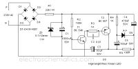
AC voltage is rectified by the full wave rectifier formed of D1 through D4.The rectified voltage is reduced to a safer level by the resistor R1.The low volt DC is then made ripple free by C1 and regulated to 5 volt DC by the Zener diode ZD. Transistor T1 and T2 form an oscillator with capacitor C3 and resistor R2. The charging and discharging of C3 through R2 makes T1 and T2 oscillating.LED connected to the positive of C5 flashes depending on the charge and discharge of C5.When C3 fully charges, T1 conducts and its collector pulls the base of T2 to ground and it also conducts. This causes the discharge of C5. When C3 discharges, T1 and T2 turns off and now C5 charges through R4.This causes the Flashing of LED.
LED Flasher Circuit diagram

Caution: Shock Hazard! This circuit is directly connected to High volt AC. Do not construct the circuit if you are not experienced in handling AC voltage. Do not touch any points when connected to mains.
AC voltage is rectified by the full wave rectifier formed of D1 through D4.The rectified voltage is reduced to a safer level by the resistor R1.The low volt DC is then made ripple free by C1 and regulated to 5 volt DC by the Zener diode ZD. Transistor T1 and T2 form an oscillator with capacitor C3 and resistor R2. The charging and discharging of C3 through R2 makes T1 and T2 oscillating.LED connected to the positive of C5 flashes depending on the charge and discharge of C5.When C3 fully charges, T1 conducts and its collector pulls the base of T2 to ground and it also conducts. This causes the discharge of C5. When C3 discharges, T1 and T2 turns off and now C5 charges through R4.This causes the Flashing of LED.
LED Flasher Circuit diagram

Caution: Shock Hazard! This circuit is directly connected to High volt AC. Do not construct the circuit if you are not experienced in handling AC voltage. Do not touch any points when connected to mains.
Son düzenleyen: Moderatör:
